
User Manual


Specifications
Chapter 4
4-7
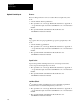
Table
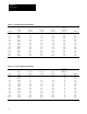
4.3 -- B003B200 Output Current and kV
A
Internal
Chassis
Component Heatsink
Heat Heat Total Minimum
Drive kVA Out kVA Out kVA Out Dissipation Dissipation Dissipation CFM
Amps Out Rating 380V AC 415V AC 460V AC (BTU/hour) n (BTU/hour) n (BTU/hour) n Required n
6.0 B003 3.9 4.3 4.8 136 239 375 15
9.6 B005 6.3 6.9 7.6 171 307 477 25
13.0 B007 8.6 9.3 10.4 273 512 784 40
17.0 B010 11.2 12.2 13.5 341 682 1023 53
25.0 B015 16.5 18.0 20.0 443 1023 1466 76
33.0 B020 22.0 24.0 26.0 477 1364 1841 95
41.0 B025 27.0 29.0 33.0 614 1705 2319 120
48.0 B030 32.0 35.0 38.0 716 2046 2762 142
60.0 B040 39.0 43.0 48.0 938 2438 3376 175
75.0 B050 49.0 54.0 60.0 1125 2847 3973 205
120.0 B075 79.0 86.0 96.0 1705 5115 6820 352
150.0 B100 99.0 108.0 120.0 2046 7502 9548 492
180.0 B125 118.0 129.0 143.0 2387 8184 10571 545
218.0 B150 143.0 157.0 174.0 2728 10912 13640 703
290.0 B200 191.0 208.0 231.0 3069 13981 17050 880
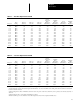
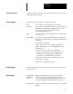
Table
4.4 -- C003C200 Output Current and kV
A
Internal
Chassis
Component Heatsink
Heat Heat Total Minimum
Drive kVA Out kVA Out kVA Out Dissipation Dissipation Dissipation CFM
Amps Out Rating 500V AC 575V AC 600V AC (BTU/hour) n (BTU/hour) n (BTU/hour) n Required n
4.3 C003 3.7 4.3 4.3 136 239 375 15
6.7 C005 5.8 6.7 6.7 171 307 477 25
9.9 C007 8.6 9.9 9.9 273 444 717 40
12.1 C010 10.5 12.1 12.1 341 512 853 45
19.0 C015 16.5 18.9 18.9 443 853 1296 60
24.0 C020 20.8 23.9 23.9 477 1023 1500 80
30.0 C025 26.0 29.9 29.9 614 1364 1978 105
35.0 C030 30.3 34.9 34.9 716 1535 2251 115
45.0 C040 39.0 44.8 44.8 938 1876 2814 145
57.0 C050 49.4 56.8 56.8 1125 2217 3342 175
85.0 C075 73.6 84.7 84.7 1705 4433 6138 320
109.0 C100 94.4 108.6 108.6 2046 5797 7843 405
138.0 C125 119.5 137.4 137.4 2387 6820 9207 475
158.0 C150 136.8 157.4 157.4 2728 8525 11253 580
210.0 C200 181.9 209.1 209.1 3069 10571 13640 703
n The above information is provided for reference only. For all ratings the user must verify that the selected enclosure will dissipate the total BTUs
generated within the enclosure without allowing the internal ambient to rise above 50°C. Enclosure mounting and location must allow for the heatsink
to extend outside the enclosure.
• When locating the drive allow a minimum clearance from other components of 4.0 inches (101.6 mm) on the top and bottom, 2.0 inches (50.8 mm) on
either side.
• When mounting the drive, ensure that the heatsink fins are vertical.
With the heatsink exposed to the ambient, the drive will dissipate heat as listed in the Output Current Table above.