
User Manual

Overview
Chapter 3
3-2
1
2
3
4
5
6
7
8
9
10
11
12
13
14
15
16
17
18
19
20
1
2
3
4
5
6
7
8
9
10
11
12
13
14
15
16
17
18
19
20
1
2
3
4
5
6
7
8
9
10
11
12
13
14
15
16
17
18
19
20
4 3 2 1
TB1
L1
L2
L3
GND
GND
1
2
3
BR1
–
+
MOV1
GND
Sense
(AC)
12
ST
L1
13
12
1
2
3
4
5
6
7
8
9
10
11
12
13
14
15
16
17
18
TB2
E1
19
20
21
22
23
24
25
26
27
28
29
30
1
2
3
4
5
6
7
8
9
10
11
12
13
14
15
16
17
18
19
20
1
2
3
4
5
6
7
8
9
10
11
12
13
14
15
16
17
18
19
20
J9 J2
J8
1
2
3
4
5
6
7
8
9
10
1
2
3
4
5
6
7
8
9
10
1
2
3
4
5
6
7
8
9
10
1
2
3
4
5
6
7
8
9
10
1
2
GND
EARTH
GROUND
CHASSIS
GROUND
SIGNAL
COMMON
+ BUS
– BUS
Main Control Board
(MAIN CTL)
J6
J1
J7
J4
Optional +5V DC TTL
Logic Interface
or
Optional 24V DC Logic
Interface
or
Optional 115V AC Logic
Interface
Programming and
Display Board
(LOCAL DIS)
Optional Logic
Control Board
(LOCAL CTL)
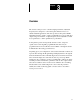
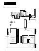
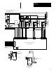
Figure
3.1 - B003B030 & C003C030 Unit Schematic
21
TB1
J1
J1
J1
J2
J2
For
Remote
Serial
Communicatio
ns
Options
1
2
3
4
5
6
7
8
9
10
11
12
13
14
15
16
17
18
19
20