Bulletin 1336 Adjustable Frequency AC Drive User Manual
Important User Information ATTENTION: Identifies information about practices or circumstances that can lead to personal injury or death, property damage or economic loss. Attentions help you: • Identify a hazard. • Avoid the hazard. • Recognize the consequences. IMPORTANT: Identifies information that is especially important for successful application and understanding of the product. DANGER labels may be located on or inside the drive to alert people that dangerous voltage may be present.
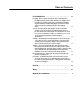
Summary of Changes Summary of Changes Summary of Manual Changes This release of the 1336-5.0 User Manual contains some new and updated information. The new and updated information is summarized in the table below. For further information, refer to the page numbers provided. Description of New or Updated Information Page Type Unit Schematics – Figures 3.1, 3.2, 3.
Table of Contents Pre Installation Care . . . . . . . . . . . . . . . . . . . . . . . . . . . . . 1 1 Receiving - Once you have received your drive, careful inspection for shipping damage must be made. Damage to the shipping carton is usually a good indication that it has received improper handling. Any and all damage should be immediately reported to the freight carrier and your nearest Allen Bradley Area Sales/Support Center. . . . . . . . . . . . . . . . . . . . . . . . . . . . . . . . . . . . . . . .
Preface Manual Objective This manual defines the installation, operation, startup and fault codes for the Allen-Bradley 1336 Adjustable Frequency AC Drive. It is intended for use by personnel familiar with the functions of solid-state drive equipment. Also provided are interconnection drawings for 1336 logic interface options in Appendix A. The 1336 User Manual is designed to be read and used like an ordinary textbook.
Preface Manual Objective (cont.) Firmware versions are marked at two locations in the drive – on the Main Control Board and on the Base Driver/Power Supply Board. For all drive ratings, the microprocessor chip U14 located on the Main Control Board has the following firmware identification: • P/N XXXXXXV1.01 –– Firmware Version 1.01. • P/N XXXXXXV1.10 –– Firmware Version 1.10. • P/N XXXXXXV1.11 –– Firmware Version 1.11. • P/N XXXXXXV2.01 –– Firmware Version 2.01.
Preface Manual Objective (cont.) For B003-B030 & C003-C030 ratings, microprocessor chip U21 located on the Base Driver/Power Supply Board has the following firmware identification: • P/N XXXXXXV1.01 –– Firmware Version 1.01. • P/N XXXXXXV1.11 –– Firmware Version 1.11. • P/N XXXXXXV1.13 –– Firmware Version 1.13. • P/N XXXXXXV1.14 –– Firmware Version 1.14. • P/N XXXXXXV3.01 –– Firmware Version 3.01.
Preface Manual Objective (cont.) For B040-B050 & C040-C050 ratings, microprocessor chip U2 located on the Base Driver/Power Supply Board has the following firmware identification: • P/N XXXXXXV1.11 –– Firmware Version 1.11. • P/N XXXXXXV1.13 –– Firmware Version 1.13. • P/N XXXXXXV1.14 –– Firmware Version 1.14. • P/N XXXXXXV3.01 –– Firmware Version 3.01.
Preface For B075-B125 & C075-C125 ratings, microprocessor chip U2 located on the Base Driver/Power Supply Board has the following firmware identification: • P/N XXXXXXV1.11 –– Firmware Version 1.11. • P/N XXXXXXV1.13 –– Firmware Version 1.13. • P/N XXXXXXV1.14 –– Firmware Version 1.14. • P/N XXXXXXV3.01 –– Firmware Version 3.01.
Preface Manual Objective (cont.) For B150-B200 & C150-C200 ratings, microprocessor chip U2 located on the Base Driver/Power Supply Board has the following firmware identification: • P/N XXXXXXV1.11 –– Firmware Version 1.11. • P/N XXXXXXV1.13 –– Firmware Version 1.13. • P/N XXXXXXV1.14 –– Firmware Version 1.14. • P/N XXXXXXV3.01 –– Firmware Version 3.01. NLY. EO WIR G UNDS ER PP ) AW PO CO (3 CH °C ZE 2 5 IN E 75 SI 27 US WIRE RQUE D TO GN ING EN HT TIG L3 NLT.
Preface Manual Objective (cont.) This manual is meant to guide the user with interface, installation, setup and troubleshooting of a 1336. The contents are arranged in order from a general description to troubleshooting and maintenance. To assure successful installation and operation, the material presented must be thoroughly read and understood before proceeding. Particular attention must be directed to the Caution, Warning and Important statements contained within.
Preface General Precautions In addition to the precautions listed throughout this manual, the following statements which are general to the system must be read and understood. ! ! ! P-8 ATTENTION: Only personnel familiar with the 1336 AC Drive and associated machinery should plan or implement the installation, start-up and subsequent maintenance of the system. Failure to comply may result in personal injury and/or equipment damage.
Chapter 1 Pre Installation Care Before installing and operating your 1336, carefully read this manual and observe all precautions. The catalog number of your drive as explained in Chapter 2 — Drive and Option Identification lists the drive rating, type of enclosure, nominal line voltage, phase and frequency, as well as any additional options that you may have specified.
Chapter 1 Pre-Installation Care ! Electrostatic Discharge Precautions ATTENTION: This assembly contains parts and sub-assemblies that are sensitive to electrostatic discharge. Static control precautions are required when servicing this assembly. Component damage may result if you ignore electrostatic discharge control procedures. If you are not familiar with static control procedures, reference Allen-Bradley Publication 8000-4.5.
Chapter 2 Drive and Option Identification The following is an explanation of the catalog numbering system for 1336 Adjustable Frequency AC Drives and options. The catalog number is coded to identify the drive power rating and can be found on the drive shipping carton. 1336 Drive Catalog Numbers 1336 B 015 EAE FA2 L2 S1 Bulletin Number Drive Rating Enclosure Type Options Options Options Bulletin Number The Allen-Bradley reference number identifying the type or family of products.
Chapter 2 Drive and Option Identification The second, third and fourth characters indicate the power rating of the drive, as shown in Tables 2.1 and 2.2. Table 2.1 - B003 B200 Output Current and kVA Rating Code B003 B005 B007 B010 B015 B020 B025 B030 B040 B050 B075 B100 B125 B150 B200 Amp Out 6.0 9.6 13.0 17.0 25.0 33.0 41.0 48.0 60.0 75.0 120.0 150.0 180.0 218.0 290.0 kVA Out 380V AC 3.9 6.3 8.6 11.2 16.5 22.0 27.0 32.0 39.0 49.0 79.0 99.0 118.0 143.0 191.0 kVA Out 415V AC 4.3 6.9 9.3 12.2 18.0 24.
Chapter 2 Drive and Option Identification Drive Enclosure Type The first character “E” indicates enclosure code. The second character indicates the type of enclosure as initially shipped from the factory. O A C J –– –– –– –– Open style (IP00) NEMA Type 1 (IP20) NEMA Type 4 (IP56) NEMA Type 12 (IP54) The third character indicates enclosure size by amp rating.
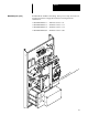
Chapter 3 Overview The 1336 is a microprocessor controlled, high performance, adjustable frequency drive designed to control three phase induction motors on critical industrial applications. The drive produces a three phase, PWM, adjustable frequency output to supply an adjustable motor speed. The drive output voltage is a function of output frequency and is adjustable to match motor parameters to obtain optimum motor performance.
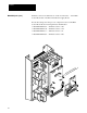
Chapter 3 Overview Figure 3.
Chapter 3 Overview Note: 1C2 & 2C2 – B025-B030 & C025-C030 Drives Only R3 & 3C1 – C003-C030 Drives Only 3C2 – C025-C030 Drives Only TB1 – DC + DC R1 M1 1C2 1C1 R2 2C1 2C2 R3 3C1 3C2 M2 MOV2 Bus Sense 1 M3 2 (AC) + Q1 – B1 Precharge M1–K K M1–AK A Q3 C1 B1 SN1 1 C1 1 SN2 SN3 J7–1 C2 J7–5 C2 E1 E1 C2 E1 E1 B2 Board G2 B1 1 E1 M1 Q2 C1 E1 B2 B2 2 2 2 AK E2 1 2 J8 1 2 3 4 5 6 7 8 9 10 1 2 3 4 5 6 7 8 J7 Q1-Q3 SN1-3 C1 1 1 2 3 1 2 3 J5 J4 E2 1
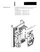
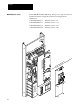
Chapter 3 Overview Figure 3.
Chapter 3 Overview Note: 1C3 & 2C3 – B040-B050 Drives Only R3, 3C1 & 3C2 – C040-C050 Drives Only 1 R1 1C1 1C2 F1 TB1 – DC 2 + DC 1 1C3 2 2 R2 2C1 2C2 2C3 3C1 B+ 3C2 M1–K M1–G1 M1 K A G2 1 1 2 M1 Bus Snubber J1 Q3 1 2 3 4 5 6 7 8 B1 Q2 C1 Q1 C1 B1 1 SN1 E1 2 B2 C2 E1 B2 Bus Sense Board C1 B1 1 C2 E1 M1–AK AK M2 MOV2 1 2 Precharge R3 M3 D2 1 SN2 E1 2 B2 C2 E1 E2 E1 E2 E2 SN3 2 E2 E2 E2 (AC) + 1 2 J8 1 2 3 4 5 6 7 8 9 10 1 2 3 4 5 6 7 8
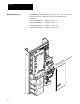
Chapter 3 Overview Figure 3.
Chapter 3 Overview TB1 – DC + DC M1 M2 LEM A + – LEM C M3 + – Note: 1C3 & 2C3 – B075-B125 Drives Only R3, 3C1 & 3C2 – C075-C125 Drives Only R1 1C1 1C2 1 1C3 F1 2 C D1 C B R2 2C1 2C2 R3 3C1 3C2 C BUS Sense C C B SN4 X4 E SN5 E B SN2 X2 – X5 E B + B SN3 X3 E 2C3 C B SN1 X1 X6 E SN6 E (AC) 1 2 J8 1 2 3 4 5 6 7 8 9 10 1 2 3 4 5 6 7 8 J7 1 2 3 4 5 6 J6 1 2 3 4 5 6 1 2 3 4 5 6 J5 J10 1 2 3 4 5 6 1 2 3 4 5 6 J4 1 2 3 4 5 6 J9 J3 1 2 3 4 5 6 J2
Chapter 3 Overview Figure 3.
Chapter 3 Overview TB1 – DC + DC LEM A + – LEM C + – Note: 1C4, 1C5, 2C4, & 2C5 B150-B200 Drives Only R2 R5 C 2 1 2 M1 M2 M3 Optional 1336-MOD-LR C B Only 1C2 1C3 1C4 1C5 1C1 C B SN1 X1 C150-C200 Drives B SN3 X3 E SN5 X5 E E 2C1 2C2 2C3 2C4 2C5 C C B R3 1 D1 2 R3, R6, 3C1, 3C2 & R4 2 F1 1 3C3 R1 1 R6 + 3C1 3C2 3C3 BUS Sense C B SN2 X2 – E B SN4 X4 SN6 X6 E E (AC) 1 2 1 2 3 4 5 6 7 8 J8 1 2 3 4 5 6 7 8 9 10 J7 1 2 3 4 5 6 J6 1 2 3 4 5 6 J5
Chapter 3 Overview The 1336 is an AC adjustable frequency drive designed for use with a standard, three-phase induction motor. The standard control is designed as a constant torque, adjustable speed control with 150% overload capability and is adaptable through programming to handle a wide variety of applications. The 1336 provides an exceptional output voltage and current waveform. Special considerations however, must be taken when applying an inverter to an existing motor.
Chapter 4 Specifications Operating Environment Temperature: Open rating (heat sink), 0 to + 40°C. Open rating (chassis components), 0 to +50°C. Enclosed rating (heat sink), 0 to + 40°C. Enclosed rating (chassis components), 0 to +50°C. Relative Humidity: 5 to 95% non-condensing –– all ratings. Storage Environment Altitude: 3,300 feet (1,000 meters) maximum without derating. Vibration: 0.006 inches (0.152 mm) displacement, 1G peak. Shock: 15G peak for 11ms duration (±1.0mS).
Chapter 4 Specifications Input Power Conditioning General Typically the 1336 is suitable for direct connection to a correct voltage, three phase, AC power line. There are however certain power line conditions which may introduce the possibility of drive input power component malfunction. To reduce the possibility of these malfunctions, a line reactor or isolation type transformer may be required. The basic rules for determining if a line reactor or isolation type transformer is required are as follows: 1.
Chapter 4 Specifications B003 B200 Input Power Voltage: 380-460V AC ±10%. Frequency: 48 to 62 Hz. Phase: 3-phase. AC Input Overvoltage Trip: 570V AC. AC Input Undervoltage Trip: 275V AC. Bus Overvoltage Trip: 810V DC for drive ratings B003-B200. Bus Undervoltage Trip: 388V DC for Base Driver/Power Supply Board. Firmware Versions 1.11-3.01. 456V DC for Base Driver/Power Supply Board. Firmware Version 1.01.
Chapter 4 Specifications Table 4.1 B003 B200 Input Current and kVA Amps In Rating Code 5.7 9.2 13.3 17.0 25.0 34.0 42.0 49.0 61.0 76.0 122.0 153.0 184.0 222.0 296.0 B003 B005 B007 B010 B015 B020 B025 B030 B040 B050 B075 B100 B125 B150 B200 Table 4.2 3.8 6.1 8.8 11.2 16.0 22.0 28.0 32.0 40.0 50.0 80.0 101.0 121.0 146.0 195.0 kVA In 415V AC 4.1 6.6 9.6 12.0 18.0 24.0 30.0 35.0 44.0 55.0 88.0 110.0 132.0 160.0 213.0 kVA In 460V AC 4.5 7.3 10.6 14.0 20.0 27.0 33.0 39.0 49.0 61.0 97.0 122.0 147.0 177.
Chapter 4 Specifications Output Power Waveform: Sine coded pulse width modulated waveform. Voltage: B003-B200 0 to applied input voltage, 380V AC, 415V AC, or 460V AC (maximum output voltage cannot exceed applied input voltage). C003-C200 0 to 575V AC (maximum output voltage cannot exceed applied input voltage). Frequency Range: 0 to 250Hz with programmable minimum and maximum limits. Frequency Resolution: Digital — Preset speeds (serial interface or pulse train input) to 0.
Chapter 4 Specifications Output Power (cont.) DC Boost: 11 selectable values from 0 to 48V DC peak. – Adjustable from 0 to 115V DC through optional programming. Accel/Decel: Two independently programmable accel times. Two independently programmable decel times. Each time may be programmed over a range from 0 to 600 seconds. Intermittent Programmable MOPC from 50 to 150% of rated output Overload Capability: current for up to 1 minute maximum.
Chapter 4 Specifications Table 4.3 -- B003 B200 Output Current and kVA Amps Out 6.0 9.6 13.0 17.0 25.0 33.0 41.0 48.0 60.0 75.0 120.0 150.0 180.0 218.0 290.0 Drive Rating B003 B005 B007 B010 B015 B020 B025 B030 B040 B050 B075 B100 B125 B150 B200 kVA Out 380V AC 3.9 6.3 8.6 11.2 16.5 22.0 27.0 32.0 39.0 49.0 79.0 99.0 118.0 143.0 191.0 kVA Out 415V AC 4.3 6.9 9.3 12.2 18.0 24.0 29.0 35.0 43.0 54.0 86.0 108.0 129.0 157.0 208.0 kVA Out 460V AC 4.8 7.6 10.4 13.5 20.0 26.0 33.0 38.0 48.0 60.0 96.0 120.
Chapter 4 Specifications Required Control Inputs As a minimum requirement for drive operation, the following five control inputs must be present to operate the drive: Start A momentary True input will start the drive. The drive will continue to run until a stop input is issued or a drive fault occurs. A start input may come from: • The optional FA2, RP2 or RP3 control panel start pushbutton. • A user supplied N.O. contact or start pushbutton connected to the optional L1, L2, or L3 Logic Interface Board.
Chapter 4 Specifications Required Control Inputs (cont.) Speed Reference Speed reference sets the drive operating frequency. A speed reference input may come from: • A Control Panel speed potentiometer. • A user supplied 10kΩ remote speed potentiometer connected to terminal block TB2. Refer to Chapter 6 — Wiring. • A 4-20mA analog signal connected to terminal block TB2. Refer to Chapter 6 — Wiring. • A 0-10V DC analog signal connected to terminal block TB2. Refer to Chapter 6 — Wiring.
Chapter 4 Specifications Optional Control Inputs Reverse Reverse changes direction of motor rotation. Reverse inputs may come from: • A Control Panel direction pushbutton. • The optional L1, L2 or L3 Logic Interface Board. Refer to Appendix A — Logic Interface Options and the 1336-MOD-L1, L2 or L3 instruction manual. • The optional G2 Remote I/O Interface Board. Refer to the 1336-MOD-G2 instruction manual. Jog Jog jogs the drive at a pre-programmed jog speed.
Chapter 4 Specifications Load Requirements A balanced 3-phase inductive motor load is typical. Other motor loads may require application assistance. Contact Outputs The following contact outputs are available as standard: Run: 1 N.O. contact, closed when the drive is running. At Speed: 1 N.O. contact, closed when the drive is at command speed (within 0.5% of maximum programmed speed), or the drive reaches the set point reference frequency programmed by Parameter 77.
Chapter 4 Specifications Programmable Parameters 4-12 The 1336 drive logic uses a set of 90 user parameters to select and control drive operation. Seventy-one of these parameters are accessible through any of the Programming and Display Panels. All 90 are accessible through the Serial Port.
Chapter 5 Installation General Installation Requirements ! ATTENTION: An incorrectly applied or installed system can result in component damage or reduction in product life. The most common causes are: • Wiring the AC line to drive output or control terminals. • Improper bypass or output circuits not approved by Allen-Bradley. • Output circuits which do not connect directly to the motor. • Incorrect or inadequate AC supply. • Excessive ambient temperature.
Chapter 5 Installation Dimensions, Weights and Conduit Entry Locations B003 B010 and C003 C010 Open Chassis and NEMA Type 1 Enclosures Open Chassis A 11.13 (283) B 18.75 (477) C 8.76 (223) D 8.38 (213) Nominal Dimensions and Weights in Inches (Millimeters) and Pounds (Kilograms) E F G H I J 18.15 1.38 0.30 6.26 2.50 — (461) (35) (8) (159) (63.5) NEMA Type 1 11.13 (283) 18.75 (477) 8.76 (223) 8.38 (213) 18.15 (461) 1.38 (35) 0.30 (8) 6.26 (159) 2.50 (63.5) 3.
Chapter 5 Installation Dimensions, Weights and Conduit Entry Locations B015 B020 and C015 C020 Open Chassis and NEMA Type 1 Enclosures Open Chassis A 11.13 (283) B 22.66 (576) C 8.76 (223) D 8.38 (213) Nominal Dimensions and Weights in Inches (Millimeters) and Pounds (Kilograms) E F G H I J 22.06 1.38 0.30 6.26 2.50 — (560) (35) (8) (159) (63.5) NEMA Type 1 11.13 (283) 22.66 (576) 8.76 (223) 8.38 (213) 22.06 (560) 1.38 (35) 0.30 (8) 6.26 (159) 2.50 (63.5) 3.
Chapter 5 Installation Dimensions, Weights and Conduit Entry Locations B025 B030 and C025 C030 Open Chassis and NEMA Type 1 Enclosures Open Chassis A 14.32 (364) B 23.59 (599) C 9.27 (235) D 11.70 (297) Nominal Dimensions and Weights in Inches (Millimeters) and Pounds (Kilograms) E F G H I J 22.41 1.31 0.59 6.64 2.63 — (570) (33.3) (15) (159) (67) NEMA Type 1 14.32 (364) 23.59 (599) 9.27 (235) 11.70 (297) 22.41 (570) 1.31 (33.3) 0.59 (15) 6.64 (159) 2.63 (67) 4.
Chapter 5 Installation Dimensions, Weights and Conduit Entry Locations B040 B050 and C040 C050 Open Chassis and NEMA Type 1 Enclosures B 34.12 (867) C 9.38 (238) D 16.25 (413) NEMA 17.50 Type 1 (445) 34.12 (867) 9.38 (238) 16.25 (413) 32.88 (835) 0.63 (16) 0.63 (16) 6.75 (172) 2.63 (67) 9.68 (246) 2.06 (52) L — M — N — O — Weight 85.0 (38.3) 2.75 (70) 2.06 (52) 1.50 (38) .63 (16) 90.0 (40.5) G I A Open 17.
Chapter 5 Installation Dimensions, Weights and Conduit Entry Locations B075 B0125 and C075 C0125 Open Chassis and NEMA Type 1 Enclosures Open Chassis A 25.16 (639) B 47.94 (1218) C 13.80 (351) D 23.88 (607) Nominal Dimensions and Weights in Inches (Millimeters) and Pounds (Kilograms) E F G H I J 46.82 0.64 0.62 10.55 3.25 — (1189) (16) (16) (268) (83) NEMA Type 1 25.16 (639) 47.94 (1218) 13.80 (351) 23.88 (607) 46.82 (1189) 0.64 (16) 0.62 (16) 10.55 (268) 3.25 (83) 9.
Chapter 5 Installation Dimensions, Weights and Conduit Entry Locations B150 B200 and C150 C200 Open Chassis and NEMA Type 1 Enclosures A Open 25.16 Chassis (639) B 62.94 (1599) C 17.50 (445) D 23.92 (608) Nominal Dimensions and Weights in Inches (Millimeters) and Pounds (Kilograms) E F G1 G2 H I J 61.82 0.62 0.62 0.50 11.75 5.75 — (1570) (16) (16) (13) (299) (146) NEMA 25.16 Type 1 (639) 62.94 (1599) 17.50 (445) 23.92 (608) 61.82 (1570) 0.62 (16) 0.62 (16) 0.50 (13) 11.75 (299) 5.
Chapter 5 Installation Dimensions, Weights and Conduit Entry Locations B003 B030 and C003 C030 NEMA Type 4 (IP56) Enclosures B003 B200 and C003 C200 NEMA Type 12 (IP54) EnclosuresNominal Dimensions and Weights in Inches (Millimeters) and Pounds (Kilograms) NEMA Type 4 (IP56) Drive Rating A B C B003-B010 32.00 C003-C010 (813) 18.00 (457) 12.75 (324) B015-B030 38.00 B015-C030 (965) 22.50 (572) 14.56 (370) NEMA Type 12 (IP54) Weight Drive Rating A B C n B003-B010 32.00 C003-C010 (813) 18.
Chapter 6 Wiring General Wiring Procedures ! ! ATTENTION: Do not proceed without reading the information on this page. Failure to understand procedures and hazards may result in personal injury or equipment damage. ATTENTION: An incorrectly applied or installed system can result in component damage or reduction in product life. The most common causes are: • Wiring the AC line to drive output or control terminals. • Improper bypass or output circuits not approved by Allen-Bradley.
Chapter 6 Wiring 7. Since most startup difficulties result from incorrect wiring, every precaution should be taken to assure that the wiring is as indicated on the diagrams and information packed with the drive. Input Power Conditioning General Typically the 1336 is suitable for direct connection to a correct voltage, three phase, AC power line. There are however certain power line conditions which may introduce the possibility of drive input power component malfunction.
Chapter 6 Wiring Wire Group Numbers The following chart identifies general wire categories that will be encountered when installing the 1336 and other AC drives. Each category has an associated wire group number that is used in the following sections to identify the wire to be used. Application and signal examples along with the recommended type of cable for each group is provided.
Chapter 6 Wiring Terminal Block TB1 Power Wiring Input and output power connections are marked on terminal block TB1, a ten position terminal block on the drive backpanel. For maintenance and setup procedures, the drive may be operated without a motor connected. Important: 1. The 1336 does not provide input power short circuit fusing. Specifications for the recommended fuse size and type to provide drive input power protection against short circuits are provided on the following pages.
Chapter 6 Wiring ! ATTENTION: 1. Any disconnecting means wired to drive output terminals M1, M2 and M3 must be capable of stopping the drive if opened during drive operation. If opened during drive operation, the drive will continue to produce output voltage into an open motor circuit causing a potential shock hazard. 2. The start/stop control circuitry in the 1336 includes solid-state components.
Chapter 6 Wiring Terminal Block TB1 B003 B030 & C003 C030 Power Wiring GND GND +DC –DC M1 M2 M3 L1 L2 USE 75°C COPPER WIRE ONLY WIRE RANGE 6–14 AWG TIGHTENING TORQUE 20 INCH POUNDS ∅A Earth Ground 1336 Dynamic Brake ∅B ∅C ❶ ❶ L3 ❶ Motor ❷ ∅A ❶ ❷ ∅B ∅C AC Incoming Line User supplied drive input fuses. Motor disconnecting means including branch circuit, short circuit, and ground fault protection. GND Chassis ground is used to connect the drive chassis to a common ground.
Chapter 6 Wiring Terminal Block TB1 B003 B030 Power Wiring Power Rating Code B003 B005 B007 B010 B015 B020 B025 B030 Drive Output Current 6.0 Amps 9.6 Amps 13.0 Amps 17.0 Amps 25.0 Amps 33.0 Amps 41.0 Amps 48.0 Amps Wire Group ❶ 2 2 2 2 2 2 2 2 Maximum Wire Size ❷ 6 AWG 6 AWG 6 AWG 6 AWG 6 AWG 6 AWG 6 AWG 6 AWG Maximum Torque ❸ 20 In-lbs 20 In-lbs 20 In-lbs 20 In-lbs 20 In-lbs 20 In-lbs 20 In-lbs 20 In-lbs ❶ Wire group number chart, page 6-3. ❷ 16 mm2. ❸ 2.26 N-m.
Chapter 6 Wiring Terminal Block TB1 B040 B050 & C040 C050 Power Wiring AC Incoming Line ∅A ∅B ∅C ❷ 1336 Dynamic Brake Earth Groun d Motor ∅A ∅B USE 75°C COPPER WIRE ONLY GND +DC –DC ❶ ∅C ❶ ❶ Earth Groun d WIRE RANGE 2/0 – 6 AWG TIGHTENING TORQUE 120 INCH POUNDS M1 M2 M3 L1 L2 GND L3 460V 380V Transform er T1 ❶ User supplied drive input fuses. ❷ Motor disconnecting means including branch circuit, short circuit, and ground fault protection.
Chapter 6 Wiring Terminal Block TB1 - B040 B050 Fan Transformer Wiring B040 B050 & C040 C050 Power Wiring (cont.) Drives rated B040-B050 are shipped from the factory with Fan Transformer T1 connected for 460V operation. Fan Transformer T1 has three leads marked 460V, 380V and 415V, each terminated by a keyed connector. For 380 or 415V drive operation, the Fan Transformer lead at L2 must be unplugged and reconnected as shown on the previous page.
Chapter 6 Wiring Terminal Block TB1 B075 & C075 Power Wiring AC Incoming Line ∅A ∅B Earth Groun d ∅C ❷ 1336 Dynamic Brake GND Motor ∅A ∅B ❶ ∅C USE 75°C COPPER WIRE ONLY ❶ ❶ WIRE RANGE 2/0 – 6 AWG TIGHTENING TORQUE 120 INCH POUNDS +DC –DC M1 M2 M3 L1 L2 L3 ❶ User supplied drive input fuses. ❷ Motor disconnecting means including branch circuit, short circuit, and ground fault protection. GND Chassis ground is used to connect the drive chassis to a common ground.
Chapter 6 Wiring Terminal Block TB1 B075 & C075 Power Wiring (cont.) B075 Fan Transformer Wiring Fan 1 Drives rated B075 are shipped from the factory with Fan Transformer T1 connected for 460V operation. Fan Transformer T1 has three tab connections marked 460V, 380V and 415V. For 380 or 415V drive operation, the Fan Transformer lead at transformer T1 must be unplugged and reconnected.
Chapter 6 Wiring Terminal Block TB1 B100 B125 & C100 C125 Power Wiring AC Incoming Line ∅A ∅B ∅C ❷ 1336 Dynamic Brake Earth Groun d GND Motor ∅A ∅B ❶ ∅C USE 75°C COPPER WIRE ONLY ❶ ❶ WIRE RANGE 350 MCM – 6 AWG TIGHTENING TORQUE 275 INCH POUNDS +DC ❶ ❷ –DC M1 M2 M3 L1 L2 L3 User supplied drive input fuses. Motor disconnecting means including branch circuit, short circuit, and ground fault protection. GND Chassis ground is used to connect the drive chassis to a common ground.
Chapter 6 Wiring Terminal Block TB1 B100 B125 & C100 C125 Power Wiring (cont.) B100 B125 Fan Transformer Wiring Drives rated B100-B125 are shipped from the factory with Fan Transformer T1 connected for 460V operation. Fan Transformer T1 has three tab connections marked 460V, 380V and 415V. For 380 or 415V drive operation, the Fan Transformer lead at transformer T1 must be unplugged and reconnected.
Chapter 6 Wiring Terminal Block TB1 B150 B200 & C150 C200 Power Wiring Earth Groun d AC Incoming Line ∅B ∅A ❷ 1336 Dynamic Brake Motor ∅A ∅B ❶ ∅C ❶ ❶ USE 75°C COPPER WIRE ONLY. WIRE RANGE 500 MCM – 0 AWG TIGHTENING TORQUE 375 INCH POUNDS USE 75°C COPPER WIRE ONLY WIRE RANGE 350 MCM – 6 AWG TIGHTENING TORQUE 275 INCH POUNDS +DC USE 75°C COPPER WIRE ONLY WIRE SIZE 2 (3) AWG TIGHTENING TORQUE 275 INCH POUNDS GND ∅C M1 –DC M2 M3 L1 L2 L3 ❶ User supplied drive input fuses.
Chapter 6 Wiring Terminal Block TB1 - L1, L2, L3 B150 B200 & C150 C200 Input AC line Terminals L1, L2, L3 (∅A, ∅B, ∅C) are not ∅ sensitive. Power Wiring (cont.) For drives rated B150-B200, nominal input voltage is 380/415/460V AC ±10%, 3∅, 50/60 Hz. For drives rated C150-C200, nominal input voltage is 500 or 575V AC ±10%, 3∅, 50/60 Hz. Branch disconnect and short circuit protection is not part of the standard 1336 and must be supplied by the user.
Chapter 6 Wiring Terminal Block TB2 and TB3 Control and Signal Wiring Terminal block TB2 is located at the bottom of the Main Control Board. TB2 is an eighteen position terminal block with markings of 1 to 18. Terminal block TB3 is a twelve position terminal block located on optional interface boards L1, L2 or L3 directly above terminal block TB2. If either L1, L2 or L3 is present, refer to Appendix A — Logic Interface Options for wiring details.
Chapter 6 Wiring Terminal Block TB2 Control and Signal Wiring The drive is capable of operating from an optional Local or Remote Control Panel with minimum connections to terminal block TB2. When required, external operator elements may be connected to provide additional drive control. Additional drive control functions and status outputs are also available for use at TB2 as detailed on the following pages. To Pulse Input ISOL To A/D 2 To A/D 1 To A/D 3 From D/A 1.4kΩ 215Ω 215Ω 100Ω 75kΩ 47.
Chapter 6 Wiring Terminal Block TB2 Control and Signal Wiring (cont.) Important: Control functions affected by drive parameter programming and selection are indicated on the following pages. Refer to the 1336 Programming Manual to verify that the drive is programmed to meet your requirements. Terminal 1 Potentiometer High Full CW or high side external potentiometer connection. Terminal 2 Potentiometer Wiper Wiper external potentiometer connection.
Chapter 6 Wiring Terminal Block TB2 Control and Signal Wiring (cont.) ! ATTENTION: Signal common is internally connected to chassis ground. User minus or user common connections to signal common must be capable of accepting this. If earth ground or cable shields are used as signal current paths, signals may be degraded. Terminal 5 and Signal Common 0-10V DC Input This terminal is provided to terminate a 0 to +10V DC speed reference signal.
Chapter 6 Wiring Terminal Block TB2 - Terminal 6 and Signal Common Control and Signal Wiring (cont.) 4-20 mA Input This terminal is provided to terminate a +4 to 20mA DC speed reference signal. Parameter 84 sets the 4-20mA signal to be either directly or inversely proportional. The minus signal is terminated at Terminals 3 or 4. The input impedance from Terminal 6 to either 3 or 4 is approximately 250Ω. The range of frequency control is between the minimum and maximum drive frequency settings.
Chapter 6 Wiring Terminal Block TB2 - Terminals 7 and 8 Control and Signal Wiring (cont.) Pulse Source Input These terminals are optically isolated and are provided to terminate a pulse train signal to the drive (Terminal 8+, Terminal 7–). When selected, the drive output frequency will be the pulse rate at Terminal 8 divided by the setting of Parameter 46, the Pulse Scale Factor. Refer to the 1336 Programming Manual for details.
Chapter 6 Wiring Terminal Block TB2 - Terminals 10 and 11 Control and Signal Wiring (cont.) At Speed These terminals allow an internal drive supplied at speed contact to be used in external circuits. Parameter 77 allows the at speed contact to be programmed to change state within ±0.5% of maximum speed for one of two conditions –– When the drive reaches command speed or when the drive reaches a programmed set point reference frequency. The contact is isolated from logic and other drive circuitry.
Chapter 6 Wiring Terminal Block TB2 - Terminals 16, 17, 18 Control and Signal Wiring (cont.) Drive Alarm These terminals allow internal drive supplied alarm contacts to be used in external circuits. The contacts are shown in the de-energized (alarm) state. When the drive is powered up and no alarm is present, the contacts will change state: 16 to 17 will open, 17 to 18 will close. Both the N.C. and N.O.
Chapter 7 Operation Freq Start PR Jog Stop PR Control Panel Enter Programming and Display Panel Important: 1336 Control Panels are not intended to replace or be considered a suitable alternative for an operator control station for all applications. If two-wire control is installed, option L1, L2 or L3 must also be installed. With two-wire control, the stop pushbutton on all Control Panels will allow the drive to restart once the button is released.
Chapter 7 Operation If this sequence is not followed, the drive will fault and display F11. When Parameter 14 is set to 0, the stop command must be repeated twice, once to clear the fault, then again to reset drive logic once the fault has been cleared. A stop input is any valid stop signal that the drive receives. Valid stop inputs are: • The Stop pushbutton on a Control Panel –– As shown on the following page.
Chapter 7 Operation Local or Remote Control Panel To allow Control Panel control: (cont.) • The Start pushbutton requires that Parameter 21 be set to on 1. • The Jog pushbutton requires that Parameter 23 be set to on 1. • The direction pushbutton requires that Parameter 22 be set to on 1. • The speed potentiometer is dependent upon the programming of Parameters 5 and 6 and the status of speed select. Speed select is controlled by TB3, Terminal 27 or serial programming.
Chapter 7 Operation Turning the speed potentiometer will adjust or set drive output frequency if the speed pot has been selected and is functional. Programming and Display Panel Freq PR PR Enter All Programming and Display Panels provide a means of displaying different drive status conditions while providing pushbutton control for selected viewing and parameter programming.
Chapter 7 Operation Fault Display Fault codes appear if the drive detects a fault condition. Freq Parameter Programming Display Parameter values appear when viewing or programming drive parameters. Freq Operating Display PR PR The Pr display is a two character display that shows the frequency source when the drive is in Standby, Jog or Running.
Chapter 7 Operation Parameter Programming A decimal point appears if parameter programming has been selected and is allowed. If the programming function is locked out, check switch SW1 on the Local Display and Programming Panel Card, option FA2. The switch must be set to C1 to allow parameter programming. Freq Fault Display Two dashes appear if a fault has occurred. Freq Special Display Enable Loss PR All dashes appear if an enable loss has occurred.
Chapter 8 Speed Selection Speed Source Priority The 1336 drive can receive speed or frequency commands from a number of sources. These sources have been given various priorities so that speed source selection may be defined and understood. The numbered speed sources shown below are listed by priority and how they are selected. Priority 1 - Jog Speed Jog may be selected if the drive is not running.
Chapter 8 Speed Selection Priority 3 - Speed Select Input Is True - Parameter 6 The speed source programmed by Parameter 6 will be selected when the speed select input at Terminal 27 is true. Parameter 6 may be programmed for one of the following six sources: Freq PR Pr = - 0 if Parameter 6 = 0, Control Panel speed potentiometer Pr = - 1 if Parameter 6 = 1, 0-10V DC input. Pr = - 2 if Parameter 6 = 2, 4-20mA input. Pr = - 3 if Parameter 6 = 3, pulse train input.
Chapter 9 Startup The following startup procedure is written for users who have a Control Panel and a Programming & Display Panel installed and who are not using a 2-wire drive control scheme. For users without a Control Panel and a Programming & Display Panel, respective external commands and signals must be substituted to simulate their operation. ! ! ATTENTION: Power must be applied to the drive with the cover removed to perform certain startup procedures.
Chapter 9 Startup Initial Operation Step 1 - Motor Disconnected Verify that AC line power at the disconnect device is within the rated value of the drive. Drive nameplate and alternate voltage ratings are listed in Chapter 2 — Drive and Option Identification. Step 2 Remove and lock out all incoming power to the drive. Remove the drive cover and disconnect motor leads from drive terminals M1, M2 and M3.
Chapter 9 Startup Initial Operation - Motor Disconnected (cont.) Important: The remaining steps in this start up procedure are based on factory parameter settings. If the drive has been previously commissioned, parameter settings may not be compatible with this start up procedure. Drive status and fault conditions will be unpredictable when power is first applied in Step 7. To obtain the proper results, initially change all parameter values to their factory settings.
Chapter 9 Startup Initial Operation Step 9a - Motor Disconnected (cont.) The PR portion of the Programming and Display Panel will indicate the speed source currently being used. Verify that the drive will accept the required speed reference sources. Freq PR Are preset speeds to be used? No – Go to Step 9b. Yes – Select preset Speed 1. Display must be - 7. Select preset Speed 5. Display must be - 9. Select preset Speed 2. Display must be - 8. Select preset Speed 6. Display must be - 9.
Chapter 9 Startup Initial Operation Step 9b - Motor Disconnected (cont.) Speed select allows switching between one of two speed references. Is the speed select function being used? No – Go to Step 9c. Yes – Close the speed select input. The display will show the speed source programmed in Parameter 6. Parameter 6 may be one of the following values. Freq PR Pr = - 0 if Parameter 6 = 0, Control Panel speed potentiometer. Pr = - 1 if Parameter 6 = 1, 0-10V DC input.
Chapter 9 Startup Initial Operation Step 9c - Motor Disconnected (cont.) The default selection or the speed source selected with the speed select open is the source programmed in Parameter 5. Parameter 5 may be one of the following values: Freq PR Pr = - 0 if Parameter 5 = 0, Control Panel speed potentiometer Pr = - 1 if Parameter 5 = 1, 0-10V DC input. Pr = - 2 if Parameter 5 = 2, 4-20mA input. Pr = - 3 if Parameter 5 = 3, pulse train input. Pr = - 4 if Parameter 5 = 4, serial input.
Chapter 9 Startup Initial Operation Step 11 - Motor Disconnected (cont.) With the Control Panel speed pot active (Pr display = - 0), turn the speed pot fully counterclockwise. Stop Start Reset the drive by pressing the Stop pushbutton. Press the Start pushbutton and start the drive. The drive will ramp to the minimum speed set by Parameter 16.
Chapter 9 Startup Initial Operation - Motor Disconnected (cont.) Step 14 Freq PR While the drive is running, open the Enable Signal at TB3, Terminal 30. The drive will stop and display the Enable Lost Code – – – - -. Restore the enable signal. Step 15 Auxiliary Interlock Check Start Restart the drive. With the drive running, open the auxiliary interlock signal at TB3, Terminal 28. The drive will stop and display the Enable Fault F02 – –.
Chapter 9 Startup Initial Operation - Motor Disconnected (cont.) Step 18 Preset Frequencies If preset frequencies are not to be used, go to Step 19. If Preset Frequencies 1-3 are used, set Parameter 72 (Activate Parameters 73-76) to 0 (Off). With the drive running, select each of the preset frequencies by closing the inputs at Terminals 24 and 26 of TB3. As each preset frequency is selected, the drive will ramp to that frequency and remain there until the next frequency is selected.
Chapter 9 Startup Initial Operation - Motor Connected ! ATTENTION: The following steps may cause motor rotation in an unknown direction. To guard against equipment damage, always disconnect the motor from the load before proceeding. Step 21 Reapply power to the drive. Minimize the possibility of incorrect motor rotation by changing the following parameters. C1 ➁ 1 SW If the chassis mounted Local Programming and Display Panel is installed, check that SW1 is in the C1 position to enable programming.
Chapter 9 Startup Initial Operation - Motor Connected (cont.) Step 23 Turn the Control Panel speed pot fully counterclockwise. Start Start the drive. Slowly increase motor speed and check for proper motor operation throughout the speed range of the drive. Step 24 With the drive operating at 1/4 speed or greater: Stop Stop the drive and verify that the stopping mode selected by Parameter 10 occurs. Step 25 Stop PR Stop the drive.
Chapter 9 Startup Initial Operation - Motor Connected (cont.) Step 26 If the drive is to receive control signals and data from a programmable controller via the MOD-G2 Remote I/O communication option, the programmable controller must be tested with the motor disconnected from the load. Prepare all drive control signal interfaces and Remote I/O option for programmable controller operation. Refer to Remote I/O Instruction Manual. Reset appropriate drive control parameters 5-50 and 72-86.
Chapter 9 Startup Initial Operation - Motor Connected (cont.) Step 27 (cont.) Apply power. Prepare to operate the drive and motor under actual control and load conditions. It is desirable to begin at low torque and speed. Start the motor and run the machine or process to determine if parameter settings are acceptable for the application. Start Stop the motor. Stop Press Pr to enter the programming mode if changes in parameter values are necessary.
Chapter 10 Fault Codes Up to 37 fault codes may be displayed for the 1336. In each instance, a Fault may be reset by cycling power to the drive, or if Parameter 39 is set to 1, by pressing the Stop pushbutton. Resetting a Fault will not correct the problem. Corrective action must be taken prior to resetting the fault. 2 Position Mode Display Area Freq PR The two character PR display is not used as part of the fault code display. However, it may be used to indicate the loss of enable.
Chapter 10 Fault Codes Auxiliary Fault Freq PR The auxiliary input interlock is open. The auxiliary interlock is: Jumper 9-10 of J9 on the Main Control Board if interface option L1, L2, L3 is not installed. Terminal 28 of TB3 if interface option L1, L2 L3 is installed. Power Loss Freq PR Occurs only if Parameter 40 is set to 0 and input power is interrupted for 0.2 seconds. Monitor the incoming AC line for low voltage or line power interruption.
Chapter 10 Fault Codes Motor Stalled Freq PR Indicates that the drive has not been able to change output frequency for: 4 seconds for drives with Base Driver/Power Supply Board Firmware Versions 1.11, 1.13, 1.14 or 2.01. 10 seconds for drives with Base Driver/Power Supply Board Firmware Versions 1.01. Conditions sensed are: Excessive Current The motor is drawing excessive current (over 150%). The motor load is excessive and will not allow the drive to accelerate to set speed.
Chapter 10 Fault Codes Open Potentiometer Freq PR An open potentiometer circuit has been detected. Check the external potentiometer circuit at TB2, Terminals 1, 2 and 3 for an open circuit. Serial Error Freq PR This Fault indicates a break in communications between the drive and the 1336-MOD-G2 Remote I/O Board. This fault is sensed only after the drive is powered up and has sensed the presence of the Remote I/O Board by establishing a communications link to the board.
Chapter 10 Fault Codes Ground Fault Freq PR A current path to earth ground has been detected at one or more of the drive output terminals. Check the motor and external wiring to the drive output terminals for a grounded condition. U VW Output Short Freq PR A short circuit has been detected between two or more of the drive output terminals. Check the motor and external wiring to the drive output terminals for a shorted condition.
Chapter 10 Fault Codes Positive Phase Transistor Short Freq PR A shorted drive transistor has been detected. Check drive output transistors, both upper and lower portions of each transistor, for a shorted condition. Precharge Open Freq PR An error has been detected in the precharge circuit that does not allow precharge to occur. Check the precharge circuit. Clear Jammed Freq PR A fault has been detected originating from the Base Driver/Power Supply Board.
Chapter 10 Fault Codes Loop Overrun Freq PR A fault has been detected originating from the Base Driver/Power Supply Board. Check all wire and cable connections to the Base Driver/Power Supply Board. Replace the Base Driver/Power Supply Board if required. Motor Mode Freq PR A fault has been detected originating from the Base Driver/Power Supply Board. Check all wire and cable connections to the Base Driver/Power Supply Board. Replace the Base Driver/Power Supply Board if required.
Chapter 10 Fault Codes Slave Timeout Freq PR A fault has been detected originating from the Base Driver/Power Supply Board. Check all wire and cable connections to the Base Driver/Power Supply Board. Replace the Base Driver/Power Supply Board if required. Hertz Error Freq PR The drive cannot find a valid frequency. Check the combinations of skip frequencies to see if they completely overlap the minimum to maximum frequency range.
Chapter 10 Fault Codes EEPROM Error Freq PR A fault has been detected originating from the Main Control Board. Check all wire and cable connections to the Main Control Board. Replace the Main Control Board if required. Retries Exceeded Freq PR The number of drive restart attempts set by Parameter 85 has been exceeded. The fault must be cleared and the drive manually reset by cycling power to the drive.
Chapter 10 Fault Codes Diagnostic Current Limit Freq PR The drive has reached 150% of rated output current –– The drive’s hardware current limit while Parameter 82 (Amp Limit Fault Enable) was on. P Jump Error Freq PR An attempt has been made to enable both P-Jump and Slip Compensation. Parameters 78-80 are used to program a custom drive output waveform (a P-jump waveform) for specific applications. Parameter 78 (Traverse Period) will enable Parameters 79 and 80 if set to a value other than 0.0.
Appendix A Logic Interface Options 1336 MOD L1 +5V DC TTL Logic Contact Closure Interface Board The Contact Closure Interface Board provides a means of interfacing various signals and commands to the 1336 drive by using contact closures. The board is self-powered and does not require a separate user power source. Plug in connectors on the Interface Board allow it to be plugged directly into connectors on the Main Control Board. Two mounting thumb screws secure the board in place.
Appendix A Logic Interface Options 1336 MOD L1 +5V DC TTL Logic Contact Closure Interface Board (cont.) 4.7kΩ 4.7kΩ 4.7kΩ 390Ω +5V DC 4.7kΩ +5V DC +5V DC 100Ω 4.7kΩ 100Ω 100Ω 390Ω +5V DC 4.7kΩ +5V DC 100Ω 390Ω 4.7kΩ 100Ω 390Ω +5V DC +5V DC 4.7kΩ +5V DC 100Ω 390Ω 4.
Appendix A Logic Interface Options 1336 MOD L1 +5V DC TTL Logic Contact Closure Interface Board (cont.) Important: Control functions affected by drive parameter programming and selection are indicated on the following pages. Refer to the 1336 Programming Manual to verify that the drive is programmed to meet your requirements. If two-wire control is installed, option L1, L2 or L3 must also be installed.
Appendix A Logic Interface Options 1336 MOD L1 +5V DC TTL Logic Contact Closure Interface Board (cont.) Terminal 19 and Interface Common Start Momentary True = Start False = Continue Last State This input will command the drive to start if all hardwired interlocks are closed. The drive will continue to run until a stop command is received, an interlock is opened, or a fault is detected. A maintained True state is not required to keep the drive running but is permitted.
Appendix A Logic Interface Options 1336 MOD L1 +5V DC TTL Logic Contact Closure Interface Board (cont.) Terminal 22 and Interface Common Jog True = Jog False = Interrupt Jog and Allow Other Functions This input will jog the drive if it is not running and interlocks permit. As long as interlocks permit and the jog command remains True, the drive will continue to run at the programmed jog frequency.
Appendix A Logic Interface Options 1336 MOD L1 +5V DC TTL Logic Contact Closure Interface Board (cont.) Terminal 27 and Interface Common Speed Select True = Select Parameter 6, Frequency Select 2 False = Select Parameter 5, Frequency Select 1 The drive speed reference can come from a variety of sources. Refer to Chapter 8 — Speed Selection for details. Terminal 28 and Interface Common (This signal must be maintained as True to permit the drive to operate from any control source.
Appendix A Logic Interface Options 1336 MOD L2 +24V DC Logic Interface Board The +24V DC Logic Interface Board provides a means of interfacing various signals and commands to the 1336 drive using +24V DC signals. A +24V DC power source must be supplied by the user for the board to operate. Plug in connectors on the +24V DC Interface Board allow it to be plugged directly into connectors on the Main Control Board. Two mounting thumb screws secure the board in place.
Appendix A Logic Interface Options 1336 MOD L2 +24V DC Logic Interface Board (cont.
Appendix A Logic Interface Options 1336 MOD L2 +24V DC Logic Interface Board (cont.) Important: Control functions affected by drive Parameter programming and selection are indicated on the following pages. Refer to the 1336 Programming Manual to verify that the drive is programmed to meet your requirements. If two-wire control is installed, option L1, L2 or L3 must also be installed.
Appendix A Logic Interface Options 1336 MOD L2 +24V DC Logic Interface Board (cont.) Terminal 20 and Interface Common (This signal must be maintained as True to permit the drive to operate from any control source.) Stop Maintained True = Not stop Momentary False = Stop Stop must be a maintained True input to permit the drive to start and run. A momentary False input of 20mS or more or any other drive stop command will initiate a drive stop sequence as programmed by Parameter 10, Stop Select.
Appendix A Logic Interface Options 1336 MOD L2 +24V DC Logic Interface Board (cont.) Terminal 24 and Interface Common SW1 True = SW1 Function Selected False = SW1 function not selected Parameters 26-31 and 72-76 define the SW1 function. Terminal 26 and Interface Common SW2 True = SW2 Function Selected False = SW2 Function Not Selected Parameters 26-31 and 72-76 define the SW2 function.
Appendix A Logic Interface Options 1336 MOD L2 +24V DC Logic Interface Board (cont.) Terminal 30 and Interface Common (This signal must be maintained as True to permit the drive to operate from any control source.) Enable Maintained True = Drive Enabled False = Disable Drive Enable must be a maintained True input to permit the drive to run and jog the motor.
Appendix A Logic Interface Options 1336 MOD L3 115V AC Logic Interface Board The 115V AC Logic Interface Board provides a means of interfacing various signals and commands to the 1336 drive using 115V AC signals. A 115V AC power source must be supplied by the user for the board to operate. Plug in connectors on the 115V AC Interface Board allow it to be plugged directly into connectors on the Main Control Board. Two mounting thumb screws secure the board in place.
Appendix A Logic Interface Options If solid state switches are used, the leakage current rating of the switch must be verified. In some instances a burden resistor may be required in the switch circuit to help ensure correct circuit operation. • For solid state switches with a leakage current less than 1mA, a burden resistor is not required. • For solid state switches with a leakage current rating of 1-5mA, a 2.5kΩ, 10W burden resistor must be used in each solid state switch circuit.
Appendix A Logic Interface Options 1336 MOD L3 115V AC Logic Interface Board (cont.) K1 5.6kΩ K3 K2 5.6kΩ 5.6kΩ 5.6kΩ K4 5.6kΩ 5.6kΩ 5.6kΩ K5 5.6kΩ 5.6kΩ K6 5.6kΩ 5.6kΩ K7 5.6kΩ 5.6kΩ K8 5.6kΩ 5.6kΩ K9 5.6kΩ 5.6kΩ 5.
Appendix A Logic Interface Options 1336 MOD L3 115V AC Logic Interface Board Important: Control functions affected by drive Parameter programming and selection are indicated on the following pages. Refer to the 1336 Programming Manual to verify that the drive is programmed to meet your requirements. If two-wire control is installed, option L1, L2 or L3 must also be installed.
Appendix A Logic Interface Options 1336 MOD L3 115V AC Logic Interface Board Terminals 21, 25, 29 Interface Common Terminals 21, 25 and 29 are used to terminate both minus or interface common signals to TB3. Terminals 21, 25 and 29 are also used to terminate any shields for cables connected to TB3. For the 1336-MOD-L3 115V AC Logic Interface Board, Terminals 21, 25 and 29 are isolated from drive signal common, chassis ground, and earth ground.
Appendix A Logic Interface Options 1336 MOD L3 115V AC Logic Interface Board Terminal 27 and Interface Common Speed Select True = Select Parameter 6, Frequency Select 2 False = Select Parameter 5, Frequency Select 1 The drive speed reference can come from a variety of sources. Refer to Chapter 8 — Speed Selection for details. Terminal 28 and Interface Common (This signal must be maintained as True to permit the drive to operate from any control source.
Publication 1336-5.0 March, 1994 Supersedes August, 1993 P/N 163733 Copyright 1994, Allen Bradley Company, Inc.