
User Manual

Installation and Wiring
Chapter 4
4-20
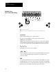
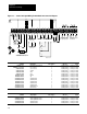
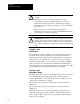
Figure 45 -- Control and Signal Wiring T
erminal Block Interconnection Diagram
Pot
1 2 3 4 5 6 7 8 9 101112131415161718
Wiper
Pot
High
Pot
Low
External
Speed Pot
+-
+-
+
-
CR1 CR2 CR3CR3
Analog Meter
4-20mA
CR1 CR3
CR3
CR2
Fault Contacts
Drive
19 20 21 22 23 24
Start Stop
Start/Stop
3Wire Control
2Wire Control
Rev
Jog
S1 S2
Reset
Lockout
Aux
Interlock
1mA
Logic
Common
S1
S2
S3
1mA Maximum when SW1 set to 1mA
SW2 set to 4SP
SW2 set to 8SP
05V
010V
10V
4SP
8SP
SW1 SW2
Programmable Outputs
End
Shield
Factory
Installed
Jumper
10V Maximum when SW1 set to 10V
Earth
Ground
Drive Input Power Applied
No Output Signal Present
Drive Input Power Applied
No Fault Present
Stop
Start
Factory
Set to
4SP
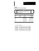
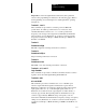
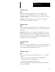
Output Signal Recommended Recommended
Terminals Output Signal Wire Group ❶ Wire Size Torque
Terminal 6 and Logic Common
01mA or 010V Meter
5
16 A
WG (1.5mm
2
) 7 InLbs (.791 Nm)
Terminals 19 and I20
CR1 Programmable Contact
3
16 A
WG (1.5mm
2
) 7 InLbs (.791 Nm)
Terminals 20 and 21
CR2 Programmable Contact
3
16 A
WG (1.5mm
2
) 7 InLbs (.791 Nm)
Terminals 22 and 23
CR3 Fault Contact
3
16 A
WG (1.5mm
2
) 7 InLbs (.791 Nm)
Terminals 23 and 24
CR3 Fault Contact
3
16 A
WG (1.5mm
2
) 7 InLbs (.791 Nm)
❶
Wire group number chart, page 46.
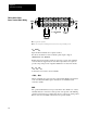
Input Signal Recommended Recommended
Terminals Input Signal Wire Group ❶ Wire Size Torque
Terminals 1, 2, 3
External Speed Potentiometer
5
16 A
WG (1.5mm
2
) 7 InLbs (.791 Nm)
Terminals 3, 8, 11 and 17
Logic Common
5
16 A
WG (1.5mm
2
) 7 InLbs (.791 Nm)
Terminals 4 and 3
05 or 010V DC
5
16 A
WG (1.5mm
2
) 7 InLbs (.791 Nm)
Terminals 5 and 3 420mA 5
16 A
WG (1.5mm
2
) 7 InLbs (.791 Nm)
Terminals 7 and 8 Start 5
16 A
WG (1.5mm
2
) 7 InLbs (.791 Nm)
Terminals 9 and 8 Stop 5
16 A
WG (1.5mm
2
) 7 InLbs (.791 Nm)
Terminals 10 and 11 Reverse 5
16 A
WG (1.5mm
2
) 7 InLbs (.791 Nm)
Terminals 12 and 11 Jog 5
16 A
WG (1.5mm
2
) 7 InLbs (.791 Nm)
Terminals 13 and 14
S1/4SP Position
5
16 A
WG (1.5mm
2
) 7 InLbs (.791 Nm)
Terminals 14 and 15
S2/4SP Position
5
16 A
WG (1.5mm
2
) 7 InLbs (.791 Nm)
Terminals 11 and 13
S1/8SP Position
5
16 A
WG (1.5mm
2
) 7 InLbs (.791 Nm)
Terminals 11 and 14
S2/8SP Position
5
16 A
WG (1.5mm
2
) 7 InLbs (.791 Nm)
Terminals 11 and 15
S3/8SP Position
5
16 A
WG (1.5mm
2
) 7 InLbs (.791 Nm)
Terminals 16 and 17 Auxiliary Interlock 5
16 A
WG (1.5mm
2
) 7 InLbs (.791 Nm)
Terminals 17 and 18
Reset Lockout
5
16 A
WG (1.5mm
2
) 7 InLbs (.791 Nm)