
User Manual


Application Data
Appendix D
D-5
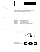
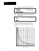
Step 5 -- Determine the Maximum Generated Braking Torque
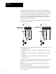
Three factors limit the application of Heavy Duty Dynamic Braking.
The first is the brake assembly rating P
T
–– The peak power the brake
assembly can absorb at any instant regardless of the time limit.
The second is the average power that the break assembly can absorb
during one braking duty cycle –– P
A
.
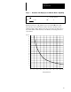
The third is the duty cycle or the number of times the brake assembly can
be operated over a given period of time –– DC.
P
M
= [ ] × [ ]
7,000
P
M
= TQ
B
×
N
2
7,000
TQ
B
= The required braking torque
N
2
= The motor'
s maximum speed
P
M
= kW
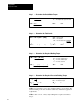
P
M
must be less than or equal to the Brake
Assembly Rating
listed in table
1
.
If P
M
exceeds the P
T
value shown, the corresponding drive/brake
configuration will not be able to produce the braking torque required for
your application, and the drive will trip on an overvoltage fault. Increasing
the decel time t
2
, reducing the load inertia wk
2
L, or doing both will lower
TQ
B
and P
M
.
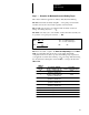
Nominal To provide the maximum To provide a
Drive HP amount of braking torque use brake assembly rating (PT) of
3/4 (1) KA1 for a 208/230VAC Unit 1.2kW
(1) KB1 for a 460VAC Unit
1 (1) KA1 for a 208/230VAC Unit 1.2kW
(1) KB1 for a 460VAC Unit
2 (1) KA2 for a 208/230VAC Unit 2.4kW
(1) KB2 for a 460VAC Unit
3 (1) KA3 for a 208/230VAC Unit 6kW
(1) KB3 for a 460VAC Unit
5 (1) KA3 for a 208/230VAC Unit 6kW
(1) KB3 for a 460VAC Unit
71/2 (1) KA4 12kW
10 (1) KA4 12kW
15 (1) KA5 24kW
20 (1) KA5 24kW
table 1