
User Manual

Application Data
Appendix D
D-2
The 1333 Series D has the ability to allow a single external 10kΩ, 2W
manual speed potentiometer and one other reference signal to be connected
to the drive at the same time. The drive may be switched from the manual
potentiometer to the alternate reference signal by means of a selector
switch. As shown in the Control and Signal Wiring section of Chapter 4,
only one of these signals should be connected to the Control and Signal
Wiring Terminal Block at any time.
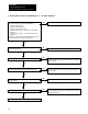
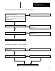
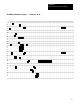
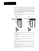
Shown below is a method of switching between an external speed pot and
one alternate reference signal.
Pot
12345
Wiper
Pot
High
Pot
Low
External
Speed Pot
Logic
Common
Drive
End
Earth
Ground
Shield
+-
4-20mA
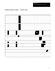
Pot
1234
Wiper
Pot
High
Pot
Low
External
Speed Pot
Logic
Common
Drive
End
Earth
Ground
Shield
+-
05V
or
05V/Speed
Pot
010V/Speed Pot
420mA/Speed Pot
or
0-10V
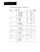
The Bulletin 1333 Series D must be programmed for external speed control
by setting Parameter 9 to:
• 1 if drive speed is to be controlled by a 0-5V DC signal or an external
speed pot.
• 2 if drive speed is to be controlled by a 0-10V DC signal or an external
speed pot.
• 3 if drive speed is to be controlled by a 4-20 mA DC signal or an
external speed pot.
When the selector switch in series with the potentiometer is open, the drive
will use the 0-5V DC, 0-10V DC, or 4-20 mA DC signal as the speed
reference.
When the selector switch is closed, the drive will use the potentiometer
signal as the speed reference.
If the selector switch is toggled while the drive is running, the drive will
accelerate or decelerate to the new speed reference at the programmed
accel or decel rate.