
User Manual

Preventive Maintenance and
Troubleshooting Common Drive Problems
Appendix B
B-8
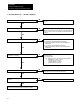
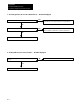
1. The motor will not run -- No fault is displayed.
Is
rated input voltage present at terminals
R
/
L1
,
S
/
L2
, and
T
/
L3
? Check input side for circuit breaker trip, contactor coil malfunction, blown
fuse,
etc.
No
Is the decimal point in the mode display lit?
Yes
The
drive is in the programming mode. Give the drive a valid stop command
and
press the lock switch. The decimal point in the mode display will light and
the local or remote control source currently controlling the drive will be
displayed.
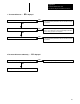
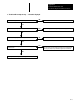
Parameter 8 settings.
0 = Local start/stop control without maintained external stop.
1 =
Remote 2wire start/stop control at the Control and Signal Wiring
Terminal Block.
2 = Local start/stop control with maintained external stop.
3 =
Remote 3wire start/stop control at the Control and Signal Wiring
Terminal Block.
Is Parameter 8 set correctly?
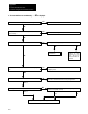
Parameter 9 settings.
0 = Local speed control.
1, 2 or 3 =
Remote speed control only at the Control and Signal Wiring
Terminal Block -- T
erms 1, 2 and 3.
1 = External speed pot or 05V DC.
2 = External speed pot or 010V DC.
3 = External speed pot or 420mA.
Is Parameter 9 set correctly?
Are Parameters 6 and 7 set correctly?
If
Parameter 6 is set to a value other than 0, Parameter 7 is active. Parameter
7
must then be set to the motors nameplate current rating.
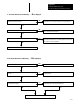
Verify and change connections if necessary.
Are the motor leads securely connected to drive output terminals
U
/
T1
,
V
/
T2
and
W
/
T3
?
Contact your nearest AB representative for application assistance.
Yes
Yes
Yes
Yes
Yes
No
No
No
No
No