
User Manual

Bulletin 1333 Options
Appendix A
A-2
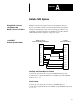
Term 3
Term 10
Term 11
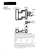
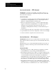
Bulletin 1333 Series D
Control and Signal Wiring Terminal Block
Term 3
1333MODG4
BCD Interface Board
Term 4
1333MODG4
BCD Interface
Drive Ratings ZABCAA
Term 4
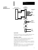
Terminal Block TB3
Term 1
Term 2
Term 5
Term 7
Term 6
Term 9
Term 8
1333MODG4
BCD Interface Board
Terminal Block TB2
Term 1
Term 2
Remote
Manual
Speed
Pot
Remote
Manual
Direction Switch
1
15V AC
Supply Signal
Remote
Auto/Man Switch
Customer Supplied
Components
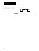
1333MODG4
BCD Interface Board
Jumper J3 set for 230V
Bulletin 1333 Series D
Power Terminal Block
Term L2/S
Term L3/T
1333MODG4
BCD Interface Board
Terminal Block TB4
Term 3
Term 1
Term 2
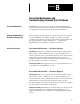
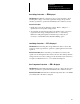
VoltsperHertz, Maximum Frequency and Base Frequency
The frequency range of the 1333-MOD-G4 BCD Interface Board and the
Bulletin 1333 Series D drive must match. Once the scaling jumper on the
BCD Interface Board has been set, Parameter 3 Frequency Range must be
set to either 60 or FF. If set to FF, both Parameter 15 Maximum Frequency
and Parameter 16 Base Frequency must also be set.
BCD Interface
Scaling Jumper
Parameter 3 Parameter 15 Parameter 16
60Hz 60 -- --
120Hz FF 60Hz 120Hz
200Hz FF 60Hz 200Hz
Important: When Parameter 3 is set to FF, the drive volts-per-Hertz output
will reach the maximum voltage at the value set by Parameter 16.
Applications where volts-per-Hertz curves are required to reach maximum
voltage other than at 50 or 60 Hz are primarily provisions for operating
custom motors. For application assistance in these special ranges, contact
your nearest Allen-Bradley representative.