
User Manual

Startup
Chapter 6
6-11
!
ATTENTION: The following steps may cause motor rotation in
an unknown direction. To guard against equipment damage, always
disconnect the motor from the load before proceeding.
Function Settings
- Motor Connected
- NoLoad Condition
Important: The remaining steps are Function Settings that reference the
same parameters as grouped in Chapter 5 –– Operation and Programming.
Step 16
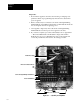
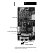
Stop the drive and remove and lock out all incoming power to the drive.
Remove the drive cover and reconnect the motor leads at terminals
U
/
T1,
V
/
T2,
W
/
T3
at the Power Terminal Block.
Step 17
Replace the drive cover and tighten both thumbscrews. Apply power to the
drive and verify that no faults are displayed.
• Both the main and mode displays should immediately light.
• The main display should read
0000. If the main display indicates OU or
LU, an incorrect voltage is being applied to the drive.
• The mode display should read
LL. to allow control of the drive from the
Local Control and Programming Panel. If not, refer to Chapter 5 to
change Parameters 8 and 9 to local control.
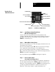
Step 18 -- VoltsperHertz Curve Settings
Overload Protection Settings
Set Parameters 3 and 4 to match your volts-per-Hertz curve and drive
frequency range requirements as detailed in Chapter 5.
If overload protection is not required, leave Parameter 6 set to 0. If
overload protection is required:
• Set Parameter 6 to correspond to the motor duty as outlined in Chapter 5.
• Set Parameter 7 to correspond to the rated amps on your motor
nameplate.