Bulletin 1333 3/4-20 HP (.
Important User Information Because of the variety of uses for this equipment and because of the differences between this solid-state equipment and electromechanical equipment, the user of and those responsible for applying this equipment must satisfy themselves as to the acceptability of each application and use of the equipment. In no event will Allen-Bradley Company be responsible or liable for indirect or consequential damages resulting from the use or application of this equipment.
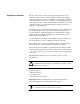
Summary of Changes Summary of Changes Summary of Manual Changes This release of the 1333-5.2 User Manual contains some new and corrected information. The new and corrected information is summarized in the table below. For further information, refer to the page numbers provided.
Table of Contents Pre Installation Care . . . . . . . . . . . . . . . . . . . . . . . . . . . . . Before installing and operating your 1333 Series D drive, carefully read this manual and observe all precautions. The catalog number of your drive as explained in Chapter 2 Drive Identification lists the drive rating, type of enclosure, nominal line voltage, phase and frequency.
Preface Manual Objective This manual defines the installation, operation, startup and fault codes for the Allen-Bradley 1333 Series D Adjustable Frequency AC Drive. It is intended for use by personnel familiar with the functions of solid-state drive equipment. Also provided are interconnection drawings for 1333 options in Appendix A, and Bulletin 1333 Series D application data in Appendix D. The 1333 Series D User Manual is designed to be read and used like an ordinary textbook.
Preface Important Information about this Manual This manual has been prepared primarily to support this product in a single application. It is a standard document that is intended to help the user understand the individual operating characteristics and limitations of this equipment including hazards associated with installation and setup procedures. Note the following points: • This equipment has been designed to meet the requirements of a component in an integrated system.
Repair/Exchange Repair or Repair/Exchange Procedure For your convenience, the Allen-Bradley Standard Drives Division, and the Allen-Bradley Support Division, provide an efficient and convenient method of returning equipment eligible for repair or repair/exchange. A product service report number is required to return any equipment for repair. This may be obtained from your local Allen-Bradley Distributor or Area Sales/Support Office.
Chapter 1 Pre Installation Care Before installing and operating your 1333 Series D drive, carefully read this manual and observe all precautions. The catalog number of your drive as explained in Chapter 2 — Drive Identification lists the drive rating, type of enclosure, nominal line voltage, phase and frequency. Specifications for all drives including standard controls, adjustment range, diagnostics and environmental qualifications are listed in Chapter 3 — Specifications.
Chapter 1 Pre-Installation Care ! Electrostatic Discharge Precautions ATTENTION: This assembly contains parts and sub-assemblies that are sensitive to electrostatic discharge. Static control precautions are required when servicing this assembly. Component damage may result if you ignore electrostatic discharge control procedures. If you are not familiar with static control procedures, reference Allen-Bradley Publication 8000-4.5.
Chapter 2 Drive Identification The following is an explanation of the catalog numbering system and information provided on the Bulletin 1333 Series D shipping carton label and drive nameplate. The 1333 Shipping Carton Label 151014 PART NO. SER. NO. A00224 ➑ BULLETIN ➐ 1333 ADJUSTABLE FREQUENCY AC DRIVE INPUT 230/208/200V, 50/60Hz OUTPUT KVA 2.0 ENCL.
Chapter 2 Drive Identification ❶ Drive Catalog Numbers 1333 Z A A Bulletin Number Drive Rating Enclosure Type Input Voltage The first letter indicates the drive rating. 200/208/230V AC, 3-Phase, 50/60 Hertz Input Voltage Rating Nominal Code HP kW ZAA AAA YAA BAA CAA DAA EAA FAA GAA 3/4 1 2 3 5 7 1/2 10 15 20 .55 .75 1.5 2.2 4 5.5 7.5 11 15 380/415/460V AC, 3-Phase, 50/60 Hertz Input Voltage Rating Nominal Code HP kW AAB YAB BAB CAB 1 2 3 5 .75 1.5 2.
Chapter 3 Specifications Operating Environment Storage Environment Temperature: –10 to + 50°C (+14 to +122°F). Relative Humidity: 5 to 95% non-condensing. Altitude: 3,300 feet (1,000 meters) maximum without derating. Vibration: Below 0.5G, 0.8 mm peak-to-peak amplitude, x-y-z direction. Shock: 16G peak for 11ms duration. Temperature: –25 to +65°C (–13 to +149°F) Relative Humidity: 5 to 95% non-condensing. Enclosure Input Power Specifications NEMA Type 1 (IP20).
Chapter 3 Specifications Standard Three Phase Data Input Current, Output Current and kVA 200/208/230V AC, 3 Phase, 50/60 Hertz Input Voltage 200V AC 208V AC 230V AC 200V AC 208V AC 230V AC Total Heat Rating Nominal Input Input Input Input Output Output Output Output Dissipated Code HP kW Amps kVA kVA kVA Amps kVA kVA kVA Watts (BTU/hr) ZAA AAA YAA BAA CAA DAA EAA FAA GAA 3/4 .55 1 .75 2 1.5 3 2.2 5 4 7 1/2 5.5 10 7.5 15 11 20 15 4.1 6.5 9.0 14.0 22.0 27.0 37.0 47.0 62.0 1.4 2.3 3.1 4.8 7.6 9.3 12.8 16.
Chapter 3 Specifications Load Requirements A balanced 3-phase inductive motor load is typical. Other motor loads may require application assistance. Output Power Specifications Waveform: Sine coded pulse width modulated waveform. Voltage: Drive Rating ZAA-GAA 0 to applied input voltage, 200V AC, 208V AC, or 230V AC –– maximum output voltage cannot exceed applied input voltage.
Chapter 3 Specifications Starting Torque: Braking Torque: 150% nominal at 5 Hz. DC Brake: 20% of rated torque (standard) programmable duration and voltage Heavy Duty Dynamic Brake: 100% of rated torque. Stopping Frequency: 0.5-60 Hz Intermittent Standard: 140% of rated output current for Overload Capability: 1 minute. Inverse Trip: 125% of programmable overload trip level for one minute.
Chapter 3 Specifications Required Control Inputs As a minimum requirement for drive operation, the following four control inputs must be present to operate the drive: Start A momentary contact closure will start the drive. The drive will continue to run until a stop input is issued or a drive fault occurs. A start input may come from: • Either of the Local Control Panel directional start pushbuttons. • A user supplied N.O. contact or start switch connected to the Control and Signal Wiring Terminal Block.
Chapter 3 Specifications Optional Remote Control Inputs The following optional inputs may be connected to the Series D Bulletin 1333 drive at the Control and Signal Wiring Terminal Block. Two or Three-Wire Start/Stop Control Forward Reverse Control Jog Three Programmable Preset Speed Select Switches Auxiliary Interlock Contact Outputs The following contact outputs are available as standard. Contacts are isolated from Logic Common and other drive circuitry and have the following ratings.
Chapter 4 Installation and Wiring General Input Power Conditioning The Series D 1333 is suitable for direct connection to a correct voltage AC power line. There are however certain power line conditions which may introduce the possibility of drive input power component malfunction. To reduce the possibility of these malfunctions, a line reactor or isolation type transformer may be required. If the use of an input transformer is desired, only an isolation type transformer should be used.
Chapter 4 Installation and Wiring ZAA CAA 230V Dimensions, Weights and Conduit Entry Locations Nominal Dimensions and Weights in Inches (Millimeters) and Pounds (Kilograms) HP kW Rating Code A B C D E F G H I J K Weight 3/4, 1 .55, .75 ZAA, AAA 8.90 (226) 10.04 (255) 4.72 (120) 8.27 (210) 9.45 (240) 0.30 (8) 0.30 (8) 2.48 (63) 1.97 (50) 2.24 (57) 1.26 (32) 6.0 (2.7) 2 1.5 YAA 8.90 (226) 11.26 (286) 5.31 (135) 8.27 (210) 10.63 (270) 0.30 (8) 0.30 (8) 2.48 (63) 1.97 (50) 2.
Chapter 4 Installation and Wiring DAA GAA 230V Dimensions, Weights and Conduit Entry Locations Nominal Dimensions and Weights in Inches (Millimeters) and Pounds (Kilograms) HP kW Rating Code A B C D E F G H I J K Weight 7 1/2, 10 5.5, 7.5 DAA, EAA 10.63 (270) 17.72 (450) 8.27 (210) 7.87 (200) 17.13 (435) 1.38 (35) 0.30 (8) 2.76 (70) 2.56 (65) 6.31 (160) 1.38 (35) 30.0 (13.6) 15, 20 FAA, GAA 10.63 (270) 21.65 (550) 8.27 (210) 7.87 (200) 21.06 (535) 1.38 (35) 0.30 (8) 2.
Chapter 4 Installation and Wiring AAB CAB 460V Dimensions, Weights and Conduit Entry Locations Nominal Dimensions and Weights in Inches (Millimeters) and Pounds (Kilograms) HP kW Rating Code A B C D E F G H I J K Weight 3/4, 1 .55, .75 AAB 8.90 (226) 11.26 (286) 5.31 (135) 8.27 (210) 10.63 (270) 0.30 (8) 0.30 (8) 2.48 (63) 1.97 (50) 2.83 (72) 1.85 (47) 9.0 (4.1) 2 1.5 YAB 8.90 (226) 11.26 (286) 5.31 (135) 8.27 (210) 10.63 (270) 0.30 (8) 0.30 (8) 2.48 (63) 1.97 (50) 2.
Chapter 4 Installation and Wiring General Wiring Procedures ! ATTENTION: Do not proceed without reading the information on this page. Failure to understand procedures and hazards may result in personal injury or equipment damage. 1. The National Electrical Code requires that a circuit breaker or fusible disconnect switch be provided in the drive branch circuit. Providing drive input fusing alone is not sufficient to meet NEC guidelines. The 1333 does not provide this requirement.
Chapter 4 Installation and Wiring Wire Group Numbers The following chart identifies general wire categories that will be encountered when installing the 1333 and other AC drives. Each category has an associated wire group number that is used in the following sections to identify the wire to be used. Application and signal examples along with the recommended type of cable for each group is provided.
Chapter 4 Installation and Wiring Terminal Block Power Wiring Important: 1. The 1333 does not provide input power short circuit fusing. Specifications for the recommended fuse size and type to provide drive input power protection against short circuits are provided on the following pages. Branch circuit breakers or disconnect switches cannot provide this level of protection for drive components. 2. Each Bulletin 1333 must have its own dedicated input and output power leads.
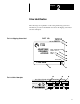
Chapter 4 Installation and Wiring 3/4 5 HP (.55 4 kW) Terminal Block Power Wiring Input and output power connections are marked on the drive Power Terminal Block. The Power Terminal Block is an eight position terminal block located at the bottom of the Main Control Board. For maintenance and setup procedures, the drive may be operated without a motor connected. Drive Input Terminals T/ L3 S/ L2 R/ L1 Drive Power Terminal Block Drive Ground Terminals Figure 4 1 -- 3/4 5 HP (.
Chapter 4 Installation and Wiring 7 1/2 20 HP (5.5 15 kW) Terminal Block Power Wiring Input and output power connections are marked on the drive Power Terminal Block. The Power Terminal Block is an eight position terminal block located at the bottom of the drive. For maintenance and setup procedures, the drive may be operated without a motor connected. Drive Output Terminals W/ T3 V/ T2 U/ T1 Drive Power Terminal Block Drive Ground Terminals Figure 4 2 -- 7 1/2 20 HP (5.
Chapter 4 Installation and Wiring ZAA EAA 3 Phase Power Terminal Block Wiring R/ L1 S/ L2 ❶ T/ L3 ❶ ❶ U/ T1 V/ T2 W/ T 3 jA jB jC Motor +BUS -BUS 1333 Dynamic Brake ❷ jA jB jC AC Incoming Line Earth Ground Earth Ground ❶ User supplied drive input fuses. ❷ Motor disconnecting means including branch circuit, short circuit, and ground-fault protection. R/ S/ T/ L1, L2, L3 Input AC line Terminals are not phase sensitive.
Chapter 4 Installation and Wiring If You Use 200/208/230V AC, 3 Phase Input Voltage CAUTION Input : 230/208VA.C. Voltage Only Use 75 Degree C ❷ AWG Copper Wire Torque to ❸ Lb-in (Power Terminal Block Cover) Power Rating Code ZAA AAA YAA BAA CAA DAA EAA Recommended Wire Size ❷ 14 AWG (2.5mm2) 14 AWG (2.5mm2) 14 AWG (2.5mm2) 12 AWG (4.0mm2) 10 AWG (6.0mm2) 8 AWG (10.0mm2) 8 AWG (10.0mm2) Wire Group ❶ 2 2 2 2 2 2 2 Recommended Torque ❸ 9 In lbs (1.02N m) 9 In lbs (1.02N m) 9 In lbs (1.02N m) 9 In lbs (1.
Chapter 4 Installation and Wiring FAA or GAA 3 Phase Power Terminal Block Wiring GND R/ S/ T/ U/ V/ W/ L L L T T T 1 2 3 1 2 3 Earth Ground ❶ ❶ ❶ jB jB GND Earth Ground jC Motor ❷ jA jA +BUS -BUS 1333 Dynamic Brake jC AC Incoming Line ❶ User supplied drive input fuses. ❶ Motor disconnecting means including branch circuit, short circuit, and ground-fault protection. R/ S/ T/ L1, L2, L3 Input AC line Terminals are not phase sensitive.
Chapter 4 Installation and Wiring If You Use FAA or GAA Units Lugs are required to terminate wires for FAA or GAA units at the Power Terminal Block. CAUTION : 230/208VA.C. Input Voltage Only Use 75 Degree C ❷ AWG Copper Wire Use U.L. Listed Crimp Connectors ❸ (Power Terminal Block Cover) Power Rating Code FAA GAA Wire Group ❶ 2 2 Recommended Wire Size ❷ 6 AWG (16.0mm2) 3 AWG (30.0mm2) ❶ Wire group number chart, page 4 6.
Chapter 4 Installation and Wiring ZAA EAA 1 Phase Power Terminal Block Wiring R/ L1 S/ L2 ❶ T/ L3 ❶ U/ T1 V/ T2 W/ T 3 jA jB jC Motor +BUS -BUS 1333 Dynamic Brake ❷ AC Incoming Line Earth Ground Earth Ground ❶ User supplied drive input fuses. ❷ Motor disconnecting means including branch circuit, short circuit, and ground-fault protection. S/ and T/ L2 L3 Input AC line Terminals are not phase sensitive.
Chapter 4 Installation and Wiring If You Use 200/208/230V AC, 1 Phase Input Voltage CAUTION : 230/208VA.C. Input Voltage Only Use 75 Degree C ❷ AWG Copper Wire Torque to ❸ Lb-in (Power Terminal Block Cover) Power Rating Code ZAA AAA YAA BAA CAA DAA EAA ❷ Wire Group ❶ 2 2 2 2 2 2 2 Recommended Wire Size ❷ 14 AWG (2.5mm2) 14 AWG (2.5mm2) 14 AWG (2.5mm2) 12 AWG (4.0mm2) 10 AWG (6.0mm2) 8 AWG (10.0mm2) 8 AWG (10.0mm2) Recommended Torque ❸ 9 In-lbs (1.02N-m) 9 In-lbs (1.02N-m) 9 In-lbs (1.
Chapter 4 Installation and Wiring FAA or GAA 1 Phase Power Terminal Block Wiring GND R/ S/ T/ U/ V/ W/ L L L T T T 1 2 3 1 2 3 Earth Ground ❶ ❶ ❷ jA jB +BUS -BUS Earth Ground jC Motor GND 1333 Dynamic Brake AC Incoming Line ❶ User supplied drive input fuses. ❷ Motor disconnecting means including branch circuit, short circuit, and ground-fault protection. S/ and T/ L2 L3 Input AC line Terminals are not phase sensitive.
Chapter 4 Installation and Wiring If You Use FAA or GAA Units Lugs are required to terminate wires for FAA or GAA units at the Power Terminal Block. CAUTION : 230/208VA.C. Input Voltage Only Use 75 Degree C ❷ AWG Copper Wire Use U.L. Listed Crimp Connectors ❸ (Power Terminal Block Cover) Power Rating Code FAA GAA ❶ ❸ Wire Group ❶ Recommended Wire Size ❷ 2 2 6 AWG (16.0mm2) 3 AWG (30.0mm2) Wire group number chart, page 4 6.
Chapter 4 Installation and Wiring Control and Signal Wiring Terminal Block The Control and Signal Wiring Terminal Block is located at the bottom of the Control Board. The Control and Signal Wiring Terminal Block is a twenty-four position terminal block with markings of 1 to 24. The drive is capable of operating from the Local Control and Programming Panel without any external control or signal connections provided the factory installed jumper at terminals 16 and 17 is installed.
Chapter 4 Installation and Wiring Drive Control Board Switches SW2 SW1 Drive Control and Signal Wiring Terminal Block Drive Ground Terminals Figure 4 4 -- 7 1/2 20 HP (5.
Chapter 4 Installation and Wiring Figure 4 5 -- Control and Signal Wiring Terminal Block Interconnection Diagram Logic Common SW1 1mA SW2 4SP 10V 6 8SP 15 Factory Set to 4SP CR1 1 2 3 4 5 Drive End Shield 7 8 Start 9 10 Stop Rev 11 12 13 Jog S1 14 S2 Pot Pot Wiper Pot High Low Start/Stop 3 Wire Control External Speed Pot 4-20mA Stop + 17 18 19 20 CR3 21 22 CR3 23 24 Factory Installed Jumper CR1 CR2 Programmable Outputs Drive Input Power Applied No Output Signal Presen
Chapter 4 Installation and Wiring Important: Control and signal functions affected by drive parameter selection and programming are indicated on the following pages. Refer to the Programming section in Chapter 5 for detailed parameter operating descriptions. Terminals 1, 2 and 3 These terminals are provided for connecting a remote 10kΩ, 2W potentiometer. To enable a potentiometer to be connected to these terminals, Parameter 9 must be set to 1, 2 or 3.
Chapter 4 Installation and Wiring ! ATTENTION: Unexpected machine acceleration can cause injury or death. If Parameter 9 is set to a value other than 0, a loss of the potentiometer low reference signal at terminal 3 of the drive terminal block will allow the drive to immediately accelerate to maximum frequency if the drive is running or a start command has been received.
Chapter 4 Installation and Wiring Terminals 7 and 8 Start This remote input will command the drive to start if all hardwired interlocks are closed and Parameter 8 is set to 1 or 3. The drive will continue to run until a stop command is received, an interlock is opened, or a fault is detected. Important: As shown in Figure 4-4, for external two wire start/stop control, terminals 7 and 8 must be jumpered.
Chapter 4 Installation and Wiring Terminals 13 and 14 -- S1/4SP Terminals 15 and 14 -- S2/4SP Switch SW2 on the Control Board is factory set to 4SP. When set to 4SP, two external switches may be connected to the drive as shown in Figure 4-3. In addition to the standard accel and decel rates set by Parameters 1 and 2, these switches may then be used to select; –– Three additional accel rates –– Four preset speeds As programmed by Parameters 19, 29-31 and 36-41.
Chapter 4 Installation and Wiring Terminals 18 and 17 Reset Lockout These terminals may be jumpered or not jumpered to determine how the 1333 is reset after a fault. When the terminals are jumpered, a drive may only be reset and restarted by removing then re-applying input power to the drive. When these terminals are left open, the drive will be reset and restarted as programmed by Parameters 47 and 48.
Chapter 4 Installation and Wiring Terminals 21 and 20 Programmable Contact CR2 These terminals allow drive supplied relay contact CR2 to be used in external circuits. When power is applied to the drive, the N.O. contact will remain N.O. until a programmed signal is received. The contact is programmed by Parameters 23 and 25 to signal that the drive is at the programmed set speed or 140% of rated drive current. The contact is isolated from Logic Common and other drive circuitry.
Chapter 5 Operation and Programming Local Control and Programming Panel The Local Control and Programming Panel provides a convenient means to locally control the operating functions of the Series D Bulletin 1333 drive including start/stop, forward/reverse, and speed. The Local Control and Programming Panel also contains two digital displays. A Main Display to show drive running values, codes, and parameter values, and a Mode Display to show the drive mode and control source.
Chapter 5 Operation and Programming The Controls The Main Display Hz LED Alternate LED The Select Pushbutton The Enter Pushbutton The Lock Switch The Stop Pushbutton The Directional Start Pushbutons The Mode Display The Increment Pushbutton The Decrement Pushbutton The Shift Pushbutton Figure 5 2 -- Bulletin 1333 Series D Controls The Select Pushbutton In the Programming Mode is used to toggle between the parameter number and the parameter value.
Chapter 5 Operation and Programming The Directional Start Pushbuttons In the Programming Mode are not functional. In the Monitoring and Operating Mode are used to start or jog the drive whenever drive speed is controlled from the Local Control Panel. The Increment and Decrement Pushbuttons In the Programming Mode are used to select parameters or increase and decrease parameter values.
Chapter 5 Operation and Programming The Displays The Main Display In the programming mode this display will show the current value of the parameter selected, flash when the value is being changed, and finally remain steady once the new value is entered. Neither the Hz nor Alternate LED will be lit in the programming mode. In the monitoring and operating mode this display can be toggled to show four operational modes.
Chapter 5 Operation and Programming The Mode Display In the programming mode the smaller two-digit display shows the parameter number selected –– 01 to 62. Whenever the drive is in the programming mode, three display items will change. 1. The display will flash. 2. The decimal point normally shown in the lower right hand corner will disappear. 3. Neither the Hz nor Alternate LED in the Main Display will be lit.
Chapter 5 Operation and Programming 5. An auxiliary interlock wired to the Control and Signal Wiring Terminal Block will stop the drive and display either A5, as set by Parameter 21. LJ To indicate the local jog function has been selected. EE To indicate: AU or 1. Drive start, jog, speed and forward/reverse is controlled by external devices or logic wired to the Control and Signal Wiring Terminal Block. 2.
Chapter 5 Operation and Programming Programming the Drive 62 parameters are available for adjusting the drive. All Series D 1333 parameters interact with each other to provide optimum drive performance. Some specific parameters however, require that other parameters be set to coordinated values if they are to function. Others require that they be set to specific values to function with Bulletin 1333 options.
Chapter 5 Operation and Programming Parameter 01 -- Acceleration Time 1 Accel and Decel Settings Units = Seconds Range = 0000/1600 Factory Setting = 005.0 This parameter determines the time that it will take the drive to accelerate over a 60 Hz change in frequency. From 0 to 0.5 Hz, the accel rate is effectively zero. From 0.5 Hz to maximum output frequency, the accel rate set by Parameter 1 will remain constant.
Chapter 5 Operation and Programming Parameter 02 -- Deceleration Time 1 Units = Seconds Range = 0000 to 1600 Factory Setting = 005.0 Important: Parameter 11 must be set to 0 to allow the drive to ramp-to-stop This parameter determines the time that it will take the drive to decelerate and ramp-to-stop over a 60 Hz change in frequency. From 0.5 to 0 Hz, the accel rate is non-linear and set by either DC injection braking or the DC dynamic brake if it is installed. From maximum output frequency to 0.
Chapter 5 Operation and Programming Volts per Hertz Curve Settings Important: The maximum allowable drive output frequency will be determined by the lowest programmed value of any of the following parameters: • Parameter 3 Frequency Range • Parameter 15 Maximum Frequency • Parameter 51 Upper Frequency Clamp • Parameter 53 Bias Frequency –– If Parameter 53 is Higher Than Parameter 54 • Parameter 54 Gain Frequency –– If Parameter 54 is Higher Than Parameter 53 Parameter 03 -- Frequency Range Units = Code
Chapter 5 Operation and Programming Parameter 04 -- Volts-per-Hertz Curve Units = Code Range = 0/1 Factory Setting = 0 This parameter sets the shape of the volts-per-Hertz ramp, either constant or curved. If set to 0, the volts-per-Hertz ramp will be linear producing a constant rate of increase from 0 to base frequency. This setting will be the setting required for most constant torque applications.
Chapter 5 Operation and Programming Overload Protection Settings Important: Parameters 6 and 7 are intended for use on single motor applications. For multiple motor applications, Parameter 6 must be set to 0 to help avoid nuisance tripping. Parameter 06 -- Motor Duty Units = Code Range = 0/1/2/3 Factory Setting = 2 Parameter 6 provides three thermal overload functions. When used in conjunction with Parameter 7, a thermal overload function that matches the motor nameplate amps can be used.
Chapter 5 Operation and Programming % of Current 140% of Rated Drive Output Current 115% of Parameter 7 Overload Protection 0 0 25 Hz 50 Hz 60 Hz Hz Maximum Frequency Parameter 6 = 1 % of Current 115% of Parameter 7 104% of Parameter 7 140% of Rated Drive Output Current 96% of Rated Drive Output Current 69% of Parameter 7 84% of Rated Drive Output Current Overload Protection 0 0 25 Hz 50 Hz 60 Hz Hz Maximum Frequency Parameter 6 = 2 % of Current 140% of Rated Drive Output Current 115%
Chapter 5 Operation and Programming Local/Remote Control Enable Important: If the Remote Operator Station option is installed, Parameter 8 must be set to 1 or 3 to allow remote control. Parameter 08 -- Local/Remote Control Units = Code Range = 0/1/2/3 Factory Setting = 0 This parameter enables or disables the drive start, jog, and forward/reverse functions as follows.
Chapter 5 Operation and Programming • An auxiliary interlock signal will stop the drive and display either AU or AS as programmed by Parameter 21. If set to 2, local control has been selected, but a maintained stop command or jumper must also be present at terminals 8 and 9 of the Control and Signal Wiring Terminal Block. If not present, all of the following commands will generate an OP error. An L will be the left-hand letter shown in the Mode Display.
Chapter 5 Operation and Programming Local/Remote Speed Enable Important: If the Remote Operator Station option is installed, Parameter 9 must be set to a value other than 0 to allow remote control. If the BCD Interface option is installed, Parameter 9 must be set to 2 to allow BCD control.
Chapter 5 Operation and Programming Reverse Enable Parameter 10 -- Reverse Lockout Units = Off/On Range = 0/1 Factory Setting = 0 This parameter enables or disables both local and remote drive direction control. If set to 0, both local and remote direction control is enabled and motor rotation can be selected in either direction. If set to 1, both local and remote direction control is locked out and motor rotation in only one direction can be selected.
Chapter 5 Operation and Programming Stop Settings Important: If the drive’s internal DC brake is enabled and/or if the Heavy Duty Dynamic Brake option is installed, Parameter 11 must be set to 0. Parameter 11 -- Stop Select Units = Code Range = 0/1 Factory Setting = 0 This parameter allows the motor to either ramp-to-stop or coast-to-stop when a stop signal is received either from the Local Control and Programming Panel, or from terminals 8 and 9 at the Control and Signal Wiring Terminal Block.
Chapter 5 Operation and Programming DC Brake Settings Parameters 12, 13 and 14 sets the DC braking action that will occur when the drive is ramped-to-stop or programmed to change direction while the drive is operating for both local and remote control. If DC braking is to be used, Parameter 11 must be set to 0, ramp-to-stop. Parameter 14 Parameter 12 Ra mp -to -St op Parameter 13 DC Break Drive Stopped DC Brake Settings Parameter 12 -- DC Hold Frequency Units = Hertz Range = 00.50/60.
Chapter 5 Operation and Programming Max Speed Settings Important: The maximum allowable drive output frequency will be determined by the lowest programmed value of any of the following parameters: • Parameter 3 Frequency Range • Parameter 15 Maximum Frequency • Parameter 51 Upper Frequency Clamp • Parameter 53 Bias Frequency –– If Parameter 53 is Higher Than Parameter 54 • Parameter 54 Gain Frequency –– If Parameter 54 is Higher Than Parameter 53 100% of Output Voltage a ler ce c A ti o n 0% 0% 100%
Chapter 5 Operation and Programming Parameter 15 -- Maximum Frequency Units = Hertz Range = 50.00/400.0 Factory Setting = 60.00 If Parameter 3 is set to 50 or 60, the drive will use the lower of the values set by Parameters 3 and 51 as the maximum drive output frequency. Parameter 15 will have no effect on drive operation. If Parameter 3 is set to FF, the drive will use the lower of the values set by Parameters 15 and 51 as the maximum drive output frequency. From 50.00-100.
Chapter 5 Operation and Programming Accel and Decel Hold Enable Important: If the Heavy Duty Dynamic Brake option is installed, decel frequency hold must be disabled by setting Parameter 18 to 0. Command Frequency n atio ➊➋ eler Acc ➊➋ ➊➋ Initial Frequency Parameter 17 = 1 Time 0 ➊ Drive output current = 140% of rated output current. ➋ Drive output current below 140% of rated output current.
Chapter 5 Operation and Programming Parameter 17 -- Accel Frequency Hold Units = Off/On Range = 0/1 Factory Setting = 1 To help avoid drive nuisance trips, this parameter enables or disables drive acceleration during high current conditions. When set to 0, accel stall protection is off. During drive acceleration, should drive output current rise above 140% of rated drive output current, the drive will trip. When set to 1, accel stall protection is on.
Chapter 5 Operation and Programming Preset Frequency and Aux Accel/Decel Enable Parameter 19 -- Frequency Select Units Range = Code = 0/1/2 Factory Setting = 0 This parameter enables or disables the selection of preset drive frequencies, auxiliary drive preset accel and decel times, or both. To allow drive preset frequencies and/or aux accel and decel times to be selected, external switches must be connected to the Control and Signal Wiring Terminal Block as detailed in Chapter 4.
Chapter 5 Operation and Programming Parameter 20 -- TB15 Preset/Reset Units Range = Code = 0/1 Factory Setting = 0 This parameter selects the control function of switch S3 when three external switches are connected to the Control and Signal Wiring Terminal Block. Parameter 20 settings. When set to 0, external switches S1, S2 and S3 connected to the Control and Signal Wiring Terminal Block can be used to select Preset Frequencies 2-8 and Accel/Decel Times 2-4.
Chapter 5 Operation and Programming As shown in Figure 4-5 in Chapter 4 –– If Parameter 19 = 0 and Parameter 20 = 0 When Control Board Switch SW2 is Set to and External Switch S1 is Set to and External Switch S2 is Set to and External Switch S3 is Set to 8SP OFF OFF OFF None 8SP ON OFF OFF Preset Frequency 2 8SP OFF ON OFF Preset Frequency 3 8SP ON ON OFF Preset Frequency 4 8SP OFF OFF ON Preset Frequency 5 8SP ON OFF ON Preset Frequency 6 8SP OFF ON ON Preset Frequenc
Chapter 5 Operation and Programming As shown in Figure 4-5 in Chapter 4 –– If Parameter 19 = 0 and Parameter 20 = 1 When Control Board Switch SW2 is Set to and External Switch S1 is Set to and External Switch S2 is Set to and External Switch S3 is Set to The Parameters Selected are 8SP OFF OFF OFF None 8SP ON OFF OFF Preset Frequency 2 8SP OFF ON OFF Preset Frequency 3 8SP ON ON OFF Preset Frequency 4 8SP OFF OFF ON Remote Fault Reset 8SP ON OFF ON Preset Frequency 2 + Rem
Chapter 5 Operation and Programming Aux Interlock Enable Parameter 21 -- Auxiliary Interlock Units = Code Range = 0/1 Factory Setting = 0 To enable drive operation, terminal 16 and logic common at the Control and Signal Wiring Terminal Block must be jumpered. This parameter sets the function of terminal 16 and logic common when a normally closed auxiliary interlock is installed in its place.
Chapter 5 Operation and Programming Drive Supplied Contact Settings Parameter 22 -- CR1 Select Units = Code Range = 1/2/3 Factory Setting = 1 This parameter sets the function of drive supplied contact CR1. CR1 is a normally open contact located at terminals 19 and 20 on the Control and Signal Wiring Terminal Block. If set to 1, the N.O contact will close when the drive is within ± 2 Hz of the run or jog set speed. If set to 2, the N.
Chapter 5 Operation and Programming Parameter 24 -- CR1 Frequency Units = Hertz Range = 00.50/400.0 Factory Setting = 00.50 This parameter sets the frequency that will cause drive supplied contact CR1 to close when Parameter 22 is set to 3. From 00.50-100.0 Hz, this parameter sets the value of CR1 Frequency in .01 Hz increments. From 100.0-400.0 Hz, this parameter sets the value of CR1 Frequency in .1 Hz increments. Parameter 25 -- CR2 Frequency Units = Hertz Range = 00.50/400.
Chapter 5 Operation and Programming Jog Settings Parameter 26 -- Jog Frequency Units = Hertz Range = 00.50/20.00 Factory Setting = 10.00 This parameter sets the jog frequency (speed) that the drive will use when it receives either a local or remote jog command. Jog frequency may be set in .01 Hz increments. Whenever the drive receives a jog command, Accel Frequency Hold, Decel Frequency Hold, and Current Limit functions are disabled.
Chapter 5 Operation and Programming Preset Frequency Settings Auxiliary Preset Frequencies are enabled or disabled by Parameters 19 and 20. Individual Preset Frequency settings are selected by setting switches S1, S2 and/or S3 as shown in Parameters 19 and 20. Parameter 29 -- Preset Frequency 2 Units = Hertz Range = 00.50/400.0 Factory Setting = 20.00 From 00.50-100.0 Hz, this parameter sets the value of Preset Frequency 2 in .01 Hz increments. From 100.0-400.
Chapter 5 Operation and Programming Parameter 32 -- Preset Frequency 5 Units = Hertz Range = 00.50/400.0 Factory Setting = 15.00 From 00.50-100.0 Hz, this parameter sets the value of Preset Frequency 5 in .01 Hz increments. From 100.0-400.0 Hz, this parameter sets the value of Preset Frequency 5 in 0.1 Hz increments. Parameter 33 -- Preset Frequency 6 Units = Hertz Range = 00.50/400.0 Factory Setting = 25.00 From 00.50-100.0 Hz, this parameter sets the value of Preset Frequency 6 in .
Chapter 5 Operation and Programming Parameter 35 -- Preset Frequency 8 Units = Hertz Range = 00.50/400.0 Factory Setting = 45.00 From 00.50-100.0 Hz, this parameter sets the value of Preset Frequency 8 in .01 Hz increments. From 100.0-400.0 Hz, this parameter sets the value of Preset Frequency 8 in 0.1 Hz increments.
Chapter 5 Operation and Programming Auxiliary Accel and Decel Settings Auxiliary Accel and Decel Times are enabled or disabled by Parameters 19 and 20. Individual Accel and Decel Parameter settings are selected by setting switches S1, S2 and/or S3 as shown in Parameters 19 and 20 Parameters 36, 38 and 40 -- Accel Times 2, 3 and 4 Units = Seconds Range = 000.1/1600 Factory Setting = 005.
Chapter 5 Operation and Programming Skip Frequency Settings Parameters 42, 43 and 44 -- Skip Frequencies 1, 2 and 3 Units = Hertz Range = 0000/400.0 Factory Setting = 0000 To help avoid undesirable mechanical resonance, Parameters 42-44 prevents the drive from running at one, two or three specific frequencies. Although the drive will use these frequencies when accelerating or decelerating, they cannot be set as ”running” frequencies by any drive parameter.
Chapter 5 Operation and Programming Parameter 45 -- Skip Frequency Band Units = Code Range = 0/10 Factory Setting = 0 Parameter 45 allows each of the individual Skip Frequencies set in Parameters 42-44 to be expanded into three bands of skip frequencies in 2-20 Hz increments. Setting a Skip Frequency Band value of 0 will disable the Skip Frequency Band function, but not individual Skip Frequency values set by Parameters 42-44.
Chapter 5 Operation and Programming Parameter 46 -- Current Limit Current Limit Setting Units = Seconds Range = 00/1.5 Factory Setting = 00 Should drive current rise above 140% of rated drive output current, the drive will attempt to limit current for one minute. Parameter 46 sets the frequency foldback rate used to decrease current in .1 second increments. Frequency foldback allows the drive to ramp output frequency down far enough to temporarily eliminate an overcurrent condition.
Chapter 5 Operation and Programming Auto Restart Settings ! ATTENTION: Auto restart operation may only be used as outlined in NFPA79, Paragraph 6-14 (exceptions 1-3) for specialized applications. Equipment damage and/or personal injury may result if the settings of Parameters 47-49 are used in an inappropriate application.
Chapter 5 Operation and Programming Parameter 48 -- Ride Thru Restart Units = Code Range = 0/1/2 Factory Setting = 0 For all control schemes, this parameter selects the drive restart action taken if input power is interrupted and restored within 100 ms. Restart settings 1 and 2 in Parameter 48 will override any settings made in Parameter 47. • When set to 0, if power is removed for 15 ms, Ride-Thru Restart is disabled and the drive will generate an LU fault.
Chapter 5 Operation and Programming Lower and Upper Frequency Clamp Settings Important: The maximum allowable drive output frequency will be determined by the lowest value programmed into the following parameters: • Parameter 3 Frequency Range • Parameter 15 Maximum Frequency • Parameter 51 Upper Frequency Clamp • Parameter 53 Bias Frequency –– If Parameter 53 is Higher Than Parameter 54 • Parameter 54 Gain Frequency –– If Parameter 54 is Higher Than Parameter 53 Parameter 50 -- Lower Frequency Clamp Uni
Chapter 5 Operation and Programming ➊ Maximum Output Frequency Parameter 51 ra ele Acc tion Parameter 50 Minimimum Frequency = 0.5 0 0% 100% of Input Frequency Signal ➊ Maximum Output Frequency Parameter 51 De cel er a tion Parameter 50 Minimimum Frequency = 0.
Chapter 5 Operation and Programming Bias and Gain Settings Important: The maximum allowable drive output frequency will be determined by the lowest programmed value of any of the following parameters: • Parameter 3 Frequency Range • Parameter 15 Maximum Frequency • Parameter 51 Upper Frequency Clamp • Parameter 53 Bias Frequency –– If Parameter 53 is Higher Than Parameter 54 • Parameter 54 Gain Frequency –– If Parameter 54 is Higher Than Parameter 53 Parameter 52 -- Bias and Gain Enable Units = Code Ra
Chapter 5 Operation and Programming ➊ 100% of Output Frequency Parameter 54 When Bias Frequency is Less Than Gain a Directly Proportional Input Frequency Signal is Produced n tio era cel c A Bias Frequency Less Than Gain Parameter 53 = 0% 0% 100% of Input Frequency Signal ➊ 100% of Output Frequency Parameter 53 Dece le r a ti o n Parameter 54 Bias Frequency Greater Than Gain 0% 0% When Bias Frequency is Greater Than Gain an Inversely Proportional Input Frequency Signal is Produced 100% of Inp
Chapter 5 Operation and Programming Output Meter Settings Parameter 55 -- Frequency Output (Amps) Units = % of Maximum Output Signal Range = 075/125 Factory Setting = 100 This parameter is used to calibrate an output frequency ammeter while the drive is running. It may be set from 75-125% of the maximum output signal, 1 mA. The 1 mA signal is selected by setting switch SW1 on the Control Board to the 1 mA position.
Chapter 5 Operation and Programming Drive Fault Memory Parameters 59, 60, 61 and 62 -- Fault Buffer 0, 1, 2, and 3 Units = None Range = None Factory Setting = None Parameters 59-62 will store the last (4) faults that the drive has encountered in a cascading mode. • Fault Buffer 0 will store the new fault. • Fault Buffer 1 will store the fault from Fault Buffer 0. • Fault Buffer 2 will store the fault from Fault Buffer 1. • Fault Buffer 3 will store the fault from Fault Buffer 2.
Chapter 6 Startup The Startup Process The following startup procedure uses the Local Control and Programming Panel to setup the drive. To guard against damage to equipment caused by incorrect or inappropriate parameter settings, steps 1-28 must be followed in order. Step 29 is provided to allow you to incorporate an external 2 or 3-wire control scheme into your application. ! ! ATTENTION: Power must be applied to the drive with the cover removed to perform certain startup procedures.
Chapter 6 Startup Important: 1. Power must be applied to the drive when viewing or changing 1333 parameters. Previous programming may effect the drive status when power is applied. 2. Remote circuits may be connected to the Control and Signal Wiring Terminal Block on the Main Control Board. Confirm that all circuits are in a de-energized state before applying power. 3. User supplied voltages may exist at the Control and Signal Wiring Terminal Block even when power is not applied to the drive. 4.
Chapter 6 Startup DC Bus Neon Light Drive Control Board Switches SW2 SW1 Control and Signal Wiring Terminal Block Power Terminal Block Auxiliary Interlock Drive Cover Thumbscrews Drive Nameplate Figure 6 2 -- 7 1/2 20 HP (5.5 15 kW) Drive 1333 parts, switches and terminal blocks shown in Figures 6-1, 6-2 and 6-3 are referenced throughout the Initial Operation, Function Checks, Function and Final Settings Sections of this chapter.
Chapter 6 Startup Initial Operation - Motor Disconnected Step 1 Verify that AC line power at the disconnect device is within the rated value of the drive nameplate data. Drive nameplate and alternate voltage ratings are explained in Chapter 2 — Drive Identification. Step 2 Remove and lock out all incoming power to the drive. Remove the drive cover and disconnect the motor leads from terminals U/T1, V/T2, W/T3 at the Power Terminal Block.
Chapter 6 Startup Function Checks - Motor Disconnected The Main Display Hz LED Alternate LED The Select Pushbutton The Lock Switch The Enter Pushbutton The Stop Pushbutton The Directional Start Pushbutons The Mode Display The Shift Pushbutton The Increment Pushbutton The Decrement Pushbutton Figure 6 3 -- 3/4 20 HP (.55 15kW) Controls Step 5 -- Local/Remote Control Enable Check Max Speed Settings Check Start the drive by pressing either directional start pushbutton. The pushbutton will light.
Chapter 6 Startup Function Checks - Motor Disconnected Step 8 -- Local/Remote Speed Enable Check Lower and Upper Frequency Clamp Settings Check Press the select pushbutton once. The main display will again flash and show the last manual set speed entered. Using the increment, decrement and shift pushbuttons, any value between 00.50 (the lower frequency clamp set by Parameter 50), and 60.00 Hz can be selected. Select a value and press the enter key.
Chapter 6 Startup Function Checks - Motor Disconnected Step 12 -- Drive Supplied Contact Settings Check Stop the drive. Remove and lock out all incoming power to the drive, then remove the drive cover. Reapply power and start the drive. N.O. contact CR2 (terms. 20 & 21 on the Control and Signal Wiring Terminal Block) will close as presently programmed by Parameter 23. Once the drive is within ± 2 Hz of set speed, N.O.
Chapter 6 Startup Function Checks - Motor Disconnected Step 13c -- Auto Restart Settings Check If Ride-Thru Restart is required, set Parameters 1 and 3. Stop the drive. • Change Parameter 48 from 0 to 1. Remove then reapply incoming power to the drive at the disconnect device within 100 ms. LU will be shown at the main display indicating a power fault. The directional start pushbutton LED will immediately light. After 10 seconds, the drive will ramp up to 60 Hz and the main display will show 60.00.
Chapter 6 Startup Step 15a -- Preset Frequency and Aux Accel/Decel Enable Check If external switches have been connected to the Control and Signal Wiring Terminal Block as detailed in Chapter 5, preset frequencies as well as auxiliary accel and decel times can be checked. Step 15b -- Preset Frequency and Aux Accel/Decel Enable Check Enable Auxiliary Accel/Decel Settings Stop the drive and depress the lock button to allow programming. Set Parameter 19 to 2.
Chapter 6 Startup Function Checks - Motor Disconnected Step 15d -- Preset Frequency and Aux Accel/Decel Enable Check If three preset speed switches have been installed, verify that switch SW2 is set to 8SP. • Closing switch S1 and opening switches S2 and S3 will force the drive to 20.00 Hz, the Preset Frequency 2 value set by Parameter 29, within the 2nd auxiliary accel time set by Parameter 36, or the 2nd auxiliary decel time set by Parameter 37.
Chapter 6 Startup Function Settings - Motor Connected - No Load Condition ! ATTENTION: The following steps may cause motor rotation in an unknown direction. To guard against equipment damage, always disconnect the motor from the load before proceeding. Important: The remaining steps are Function Settings that reference the same parameters as grouped in Chapter 5 –– Operation and Programming. Step 16 Stop the drive and remove and lock out all incoming power to the drive.
Chapter 6 Startup Function Settings Step 19 - Motor Connected - No Load Condition Press the shift pushbutton once and LJ. will be shown in the mode display. Press and release the directional start pushbutton that will be your forward motor direction. If the direction of motor rotation is incorrect: • Remove input power, wait until the displays are no longer lit, then remove the drive cover.
Chapter 6 Startup Final Settings - Motor Connected - Load Connected ! ATTENTION: To avoid hazards of electrical shock or injury from moving equipment, product, or process ingredients: • Alert all personnel. • Install all guards. • Check operation of all safety devices. • Be prepared to stop the motor immediately. Step 21 Disconnect and lock-out all power. Connect the motor to the load. Before applying power, review the parameter descriptions in Chapter 5.
Chapter 6 Startup Final Settings - Motor Connected - Load Connected Step 24 If Heavy Duty Dynamic Braking is to be Installed If Heavy Duty Dynamic braking is required, set Parameters 11 and 14 to 0. Step 25 If Machine Resonance is Encountered Set Parameters 42-45 to skip those frequencies which cause the machine to resonate. Step 26 If Nuisance Tripping is Encountered Enable Parameters 17 and/or 18 to disable drive acceleration or deceleration during high Bus current or voltage conditions.
Appendix A Bulletin 1333 Options Using Bulletin 1332 and 1333 Options with Bulletin 1333 Series D Drives 1332 MOD F Remote Operator Station Bulletin 1332 and 1333 Options can be used with Series D drives. Point-to-point interconnections and the required Series D parameter settings are detailed below and on the following pages. Refer to the individual option kit instructions for installation procedures and the additional information required to setup each option.
Appendix A Bulletin 1333 Options 1333 MOD G4 BCD Interface Drive Ratings ZAB CAA Bulletin 1333 Series D Control and Signal Wiring Terminal Block 1333 MOD G4 BCD Interface Board Terminal Block TB3 Customer Supplied Components Term 1 Term 2 Term 3 Term 3 Term 4 Term 4 Remote Manual Speed Pot Term 5 Remote Manual Direction Switch Term 6 Term 7 Term 8 Term 9 Term 10 1333 MOD G4 BCD Interface Board Terminal Block TB2 Term 11 115V AC Supply Signal Remote Auto/Man Switch Term 1 Term 2 1333 MOD G4 B
Appendix A Bulletin 1333 Options 1333 MOD G4 BCD Interface Drive Ratings AAB CAB Bulletin 1333 Series D Control and Signal Wiring Terminal Block 1333 MOD G4 BCD Interface Board Terminal Block TB3 Term 1 Term 2 Term 3 Term 3 Term 4 Term 4 Term 5 Term 6 Term 7 Term 8 Customer Supplied Components Remote Manual Speed Pot Remote Manual Direction Switch Term 9 Term 10 Term 11 1333 MOD G4 BCD Interface Board Terminal Block TB2 Term 1 Term 2 115V AC Supply Signal Remote Auto/Man Switch 1333 MOD G4 BCD I
Appendix A Bulletin 1333 Options 1333 MOD KA1, KA2, KB1, KB2 Heavy Duty Dynamic Braking Bulletin 1333 Series D Power Terminal Block Term +BUS P Term -BUS N Dynamic Brake Unit Stop Setting If Heavy Duty Dynamic Braking is installed, Parameters 11 and 14 must be set to 0.
Appendix B Preventive Maintenance and Troubleshooting Common Drive Problems Preventive Maintenance The Bulletin 1333 is convection cooled by air flowing through the heat sink slots. The slots must never be allowed to become obstructed with dirt or foreign matter. Periodically check and clean the heat sink slots. Problems with Your Drive? Check the Following First The following descriptions indicate the operation of protective circuitry in the Series D Bulletin 1333.
Appendix B Preventive Maintenance and Troubleshooting Common Drive Problems Over Current Protection -- OC is Displayed The Reason If overcurrent exceeds 200% of rated Drive current or if a ground fault occurs at the drive output leads, this protective circuit will shut off the drive transistors. Precheck Procedure 1. Load inertia is excessively large and programmed acceleration time is extremely short. Setting Parameter 17 to 1 or increasing the value of Parameter 1 will guard against OC nuisance trips. 2.
Appendix B Preventive Maintenance and Troubleshooting Common Drive Problems Over Voltage Protection -- OU Displayed The Reason When DC bus voltage rises above a preset level due to high incoming line voltage or excessive regenerative energy, this protective circuit stops transistor operation and annunciates the condition as shown. Precheck Procedure 1. Check and correct the incoming line voltage. Refer to Chapter 3 –– Specifications for acceptable voltage levels. 2.
Appendix B Preventive Maintenance and Troubleshooting Common Drive Problems Auxiliary Interlock Trip -- AU is Displayed The Reason It is possible that the drive was stopped by an external interlock. External interlocks (a thermal overload relay or an external sequence circuit for example), are connected to terminals 16 and 17 at the Control and Signal Wiring Terminal Block. Precheck Procedure Refer to Chapter 4 Installation and Wiring for a detailed explanation of external interlocks.
Appendix B Preventive Maintenance and Troubleshooting Common Drive Problems Troubleshooting Common Drive Problems Eight common problems that may be experienced when operating the Series D Bulletin 1333 and their solutions are listed in the remaining pages of this section. 1. The motor will not run. 2. The motor will not run continuously. 3. The motor generates an excessive amount of heat 4. The drive will not reverse in local control. 5. The drive will not ramp-to-stop. 6.
Appendix B Preventive Maintenance and Troubleshooting Common Drive Problems DC Bus Neon Light Lock Switch Control and Signal Wiring Terminal Block Power Terminal Block Drive Nameplate Auxiliary Interlock Figure B 1 -- 3/4 5 HP (.55 4kW) 1333 parts, switches and terminal blocks shown in Figures B-1 and B-2 are referenced throughout the remainder of this chapter. 1. The motor will not run -- AU is displayed.
Appendix B Preventive Maintenance and Troubleshooting Common Drive Problems DC Bus Neon Light Lock Switch Control and Signal Wiring Terminal Block Auxiliary Interlock Power Terminal Block Drive Nameplate Figure B 2 -- 7 1/2 20 HP (5.5 15kW) 1. The motor will not run -- OH is displayed. Is ambient temperature above the rated limit of 505C? Are the cooling fins clogged or is the heat sink dirty? For 7 1/2 20 HP (5.
Appendix B Preventive Maintenance and Troubleshooting Common Drive Problems 1. The motor will not run -- No fault is displayed. Is rated input voltage present at terminals R/L1, S/L2, and T/L3? No Check input side for circuit breaker trip, contactor coil malfunction, blown fuse, etc. Yes Is the decimal point in the mode display lit? No The drive is in the programming mode. Give the drive a valid stop command and press the lock switch.
Appendix B Preventive Maintenance and Troubleshooting Common Drive Problems 1. The motor will not run -- OP is displayed. Is Parameter 8 Local/Remote Control set to 1 (external control)? Yes No Yes Is Parameter 8 Local/Remote Control set to 2 (local control)? No Is Parameter 8 Local/Remote Control set to 3 (external control)? 2. The motor will not run continuously -- Yes The drive is set for 2 wire external control. Check for correct wiring at the Control and Signal Wiring Terminal Block.
Appendix B Preventive Maintenance and Troubleshooting Common Drive Problems 2. The motor will not run continuously -- OC is displayed. Does a short circuit exist in the output leads or motor windings? Yes Remove the cause of the short circuit. No Does a ground fault exist between the drive output leads and the motor or in the motor windings? Yes Remove the cause of the ground fault. No Does the drive trip when the speed reference is below 5.
Appendix B Preventive Maintenance and Troubleshooting Common Drive Problems 2. The motor will not run continuously -- OL is displayed. Is the load current equal to the motor nameplate rating? Is the load current within the rated current of the drive? No An OL trip occurs when the load current is greater than 140% for one minute. Lighten the load or resize the drive and motor to meet your application.
Appendix B Preventive Maintenance and Troubleshooting Common Drive Problems 3. The motor generates an excessive amount of heat -- No fault is displayed. Is full load demanded continuously at low frequency? Yes An OL trip occurs when the load current is greater than 140% for one minute. Lighten the load or resize the drive and motor to meet your application. No Is the motor operating above the full load current? Yes The load is beyond the motor capacity. Check the mechanical installation.
Appendix B Preventive Maintenance and Troubleshooting Common Drive Problems 5. The drive will not ramp to stop -- No fault is displayed. Is Parameter 11 Stop Select set to ramp to stop? No Set Parameter 11 to 0. Yes Does Parameter 59 show an OU fault stored? Yes The drive is tripping on overvoltage during decel. Refer to page B 3. No Is the DC Hold Frequency set to high -- Is parameter 12 set to 00.50 Hz? No Set Parameter 12 to 00.50 Hz.
Appendix B Preventive Maintenance and Troubleshooting Common Drive Problems 6. The drive will not accelerate to maximum speed -- No fault is displayed. The maximum allowable drive output frequency will be determined by the lowest programmed value of any of the following parameters: No Reset Parameters 3 and/or 15.
Appendix B Preventive Maintenance and Troubleshooting Common Drive Problems 7. The drive will not decelerate to minimum speed -- No fault is displayed. The priority used by the 1333 to limit minimum output frequency is: 1. For local speed control, use Parameter 50. 2 If an external potentiometer, 0 5V DC, 0 10V DC or 4 20mA signal is to control drive speed, use the higher of the values set by Parameters 15 and 51.
Appendix C Factory and Field Parameter Settings Parameters Grouped by Function The following tables in Appendix C provide parameter data grouped by function. The function groups listed, reference the same parameters as grouped in Chapters 5 and 6 and Appendix B. Factory and Field Parameter Settings -- Pages C2 and C3 The table on the left provides parameter units, min/max values, factory settings and room to record field settings.
Appendix C Factory and Field Parameter Settings Factory and Field Parameter Settings -- Parameters 01 28 Function Group Parameter Parameter Number Name Range Seconds Seconds 0000/1600 0000/1600 005.0 005.
Appendix C Factory and Field Parameter Settings Coordinated Parameter Settings -- Parameters 01 28 01 02 03 04 05 06 07 08 09 10 11 12 13 14 15 16 17 18 19 20 21 22 23 24 25 26 27 28 29 30 31 32 33 34 35 36 37 38 39 40 41 42 43 44 45 46 47 48 49 50 51 52 53 54 55 56 57 58 59 60 61 62 0I 02 03 04 05 06 07 08 09 I0 II I2 I3 I4 I5 I6 I7 I8 I9 20 2I 22 23 24 25 26 27 28 C-3
Appendix C Factory and Field Parameter Settings Factory and Field Parameter Settings -- Parameters 29 62 Function Group C-4 Parameter Parameter Number Name Factory Field Setting Setting Units Range Hertz Hertz Hertz Hertz Hertz Hertz Hertz 00.50/400.0 00.50/400.0 00.50/400.0 00.50/400.0 00.50/400.0 00.50/400.0 00.50/400.0 20.00 30.00 40.00 15.00 25.00 35.00 45.00 Seconds Seconds Seconds Seconds Seconds Seconds 000.1/1600 000.1/1600 000.1/1600 000.1/1600 000.1/1600 000.1/1600 005.0 005.0 005.
Appendix C Factory and Field Parameter Settings Coordinated Parameter Settings -- Parameters 29 62 01 02 03 04 05 06 07 08 09 10 11 12 13 14 15 16 17 18 19 20 21 22 23 24 25 26 27 28 29 30 31 32 33 34 35 36 37 38 39 40 41 42 43 44 45 46 47 48 49 50 51 52 53 54 55 56 57 58 59 60 61 62 29 30 3 I 32 33 34 35 36 37 38 39 40 4 I 42 43 44 45 46 47 48 49 50 5 I 52 53 54 55 56 57 58 59 60 6 I 62 C-5
Appendix D Application Data Important User Information Because of the variety of uses for this equipment and because of the differences between this solid state equipment and electromechanical equipment, the user of and those responsible for applying this equipment must satisfy themselves as to the acceptability of each application and use of the equipment.
Appendix D Application Data The 1333 Series D has the ability to allow a single external 10kΩ, 2W manual speed potentiometer and one other reference signal to be connected to the drive at the same time. The drive may be switched from the manual potentiometer to the alternate reference signal by means of a selector switch. As shown in the Control and Signal Wiring section of Chapter 4, only one of these signals should be connected to the Control and Signal Wiring Terminal Block at any time.
Appendix D Application Data Bulletin 1333 Heavy Duty Dynamic Braking The Bulletin 1333 Adjustable Frequency Drive has the ability to let a connected motor generate braking torque. This ability however, is limited to approximately 20% of the drive rated braking torque. The braking torque can be increased by adding one or more Bulletin 1333 heavy duty dynamic braking kits to the drive. Typically the braking torque can be increased to 100% for 20 seconds at a duty cycle of 20%.
Appendix D Application Data Step 1 -- Determine the Rated Motor Torque TQM = 5250 × HP N HP = The nameplate horsepower of the motor N = The nameplate base speed of the motor TQM = 5250 × TQM = LB FT Step 2 -- Determine the Total Inertia wk2t = wk2M + [wk2L × (GR)2] wk2t = wk2M = The motor inertia wk2L = The load inertia GR = The total reduction ratio Output RPM Input RPM )2 ] ×( + [ LB FT2 wk2t = Step 3 -- Determine the Required Braking Torque TQB = wk2t × [N2 - N1] 308 × t2 TQB = [ ] ×[ 308
Appendix D Application Data Step 5 -- Determine the Maximum Generated Braking Torque Three factors limit the application of Heavy Duty Dynamic Braking. The first is the brake assembly rating PT –– The peak power the brake assembly can absorb at any instant regardless of the time limit. The second is the average power that the break assembly can absorb during one braking duty cycle –– PA. The third is the duty cycle or the number of times the brake assembly can be operated over a given period of time –– DC.
Appendix D Application Data Step 6 -- Determine the Average Power Generated in One Cycle PA = TQB × [N1 + N2] 14,000 ] ×[ PA = [ TQB = The required braking torque N1 = The motor's minimum speed N2 = The motor's maximum speed + PA = ] kW 14,000 Step 7 -- Determine the Ratio of the Average Power to the Brake Assembly Rating P% = PA PT P% = [ [ PA = The average power generated in one cycle PT = The brake assembly rating from table 1 ] ] P% = % Find the intersection of P% and the motor’s decel tim
Appendix D Application Data Step 8 -- Determine if the Duty Cycle is within the Brake's Capability DC = t2 × 100 t1 T1 = The motor's cycle time T2 = The motor's decel time ] × 100 ] DC = [ [ DC = % Find the intersection of P% and the motor’s decel time DC in the chart below. If the point of intersection is below the curve, the duty cycle is within the brake’s limits.
Appendix D Application Data Notes D-8
We Want Our Manuals to be the Best! You can help! Our manuals must meet the needs of you, the user. This is your opportunity to make sure they do just that. By filling out this form you can help us provide the most useful, thorough, and accurate manuals available. Please take a few minutes to tell us what you think. Then mail this form, FAX it, or send comments via E-Mail. FAX: to your local Allen-Bradley Sales Office or 414/242-8201 E-Mail: via Internet to “SEPATTER@ABPOST.remnet.ab.
FOLD HERE FOLD HERE NO POSTAGE NECESSARY IF MAILED IN THE UNITED STATES BUSINESS REPLY MAIL FIRST CLASS PERMIT NO. 413 MEQUON, WI POSTAGE WILL BE PAID BY ADDRESSEE ALLEN-BRADLEY Attn: Marketing Communications P.O.
Publication 1333-5.2 July 1994 Supersedes February 1994 and 1333-5.2DU1 DU2 April 1994 P/N 152783 Copyright 1994, Allen Bradley Company, Inc.