Installation, Operation and Maintenance Manual AC Induction Motors • 56 - 5000 Frame Manufactured for Allen-Bradley by Marathon Electric, Inc.
AC Induction Motors Contents General Information Acceptance . . . . . . . . . . . . . . . . . . . . . . . . . . . . . . . . . . . . . 2 Storage . . . . . . . . . . . . . . . . . . . . . . . . . . . . . . . . . . . . . . . . 3 Installation Uncrating and Inspection . . . . . . . . . . . . . . . . . . . . . . . . . . . 3 Safety . . . . . . . . . . . . . . . . . . . . . . . . . . . . . . . . . . . . . . . . . . 3 Location . . . . . . . . . . . . . . . . . . . . . . . . . . . . . . . . . . . . . . . .
AC Induction Motors 3 Storage 1. Keep motors clean. • Store indoors. • Keep covered to eliminate airborne dust and dirt. • Cover openings for ventilation, conduit connections, etc.to prevent entry of rodents, snakes, birds, and insects, etc. 2. Keep motors dry. • Store in a dry area indoors. • Temperature swings should be minimal to guard against condensation. • Space heaters are recommended to prevent condensation. • Treat unpainted flanges, shafts, and fittings with a rust inhibitor.
AC Induction Motors Location In selecting a location for the motor, consideration should be given to environment and ventilation. A motor with the proper enclosure for the expected operating condition should be selected. The ambient temperature of the air surrounding the motor should not exceed 40˚C (104˚F) unless the motor has been specially designed for high ambient temperature applications. The free flow of air around the motor should not be obstructed.
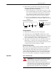
AC Induction Motors 5 Direct Connected Drive Flexible or solid shaft couplings must be properly aligned for satisfactory operation. On flexible couplings, the clearance between the ends of the shafts should be in accordance with the coupling manufacturer’s recommendations or NEMA standards for end play and limited travel in coupling. MISALIGNMENT and RUN-OUT between direct connected shafts will cause increased bearing loads and vibration even when the connection is made by means of a flexible coupling.
AC Induction Motors 1. All wiring, fusing, and grounding must comply with National Electrical Codes and local codes. 2. To determine proper wiring, rotation and voltage connections, refer to the information and diagram on the nameplate, separate connection plate or decal. If the plate or decal has been removed, contact manufacturer for assistance. 3. Use the proper size of line current protection and motor controls as required by the National Electrical Code and local codes.
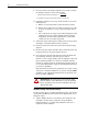
AC Induction Motors 7 3. Motors that are provided with overheat protective device that does not open the motor circuit directly will indicate “WITH OVERHEAT PROTECTIVE DEVICE.” a. Motors with this type of “Overheat Protective Device” have protector leads brought out in the motor conduit box marked “P1” and “P2.” These leads are intended for connection in series with the stop button of the 3-wire pilot circuit for the magnetic starter which controls the motor. See diagram. b.
AC Induction Motors 1. If a motor has become damp in shipment or in storage, measure the insulation resistance of the stator winding. Minimum Insulation Resistance (in Megohms) = 1 + Rated Voltage 1000 Do not attempt to run the motor if the insulation resistance is below this value. 2. If insulation resistance is low, dry out the moisture in one of the following ways: a. Bake in oven at temperature not more than 90˚C (194˚F). b. Enclose motor with canvas or similar covering.
AC Induction Motors 9 2. Frequency: Within 5% above or below the value stamped on the nameplate. 3. Voltage and Frequency together: Within 10% (providing frequency above is less than 5%) above or below values stamped on the nameplate. Cleanliness Keep both the interior and exterior of the motor free from dirt, water, oil and grease. Motors operating in dirty places should be periodically disassembled and thoroughly cleaned.
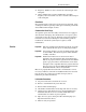
AC Induction Motors Relubrication Time Interval & Amounts - motors with regreasing provisions NEMA Frame Size 1 140-180 1800 RPM Over 1800 Service RPM Condition & Less Standard 3 years 6 months Severe 1 year 3 months Seasonal See Note 2. 1 2 210-360 1800 RPM & Less 2 years 1 year Over 1800 RPM 6 months 3 months 400-510 1800 RPM & less 1 year 6 months Over 1800 RPM 3 months 1 month For motors nameplated as “belted duty only” divide the intervals by 3. Lubricate at the beginning of the season.
AC Induction Motors • • 11 The fuses and other protective devices are in proper condition. All connections and contacts are properly made in the circuits between the control apparatus and motor. Motor Troubleshooting Chart These instructions do not cover all details or variations in equipment nor provide for every possible condition to be met in connection with installation, operation or maintenance.
Trouble Motor vibrates AC Induction Motors Cause Motor misaligned Weak support Coupling out of balance Driven equipment unbalanced Defective bearings Bearings not in line Balancing weights shifted Polyphase motor running single phase Excessive end play Unbalanced line current on Unequal terminal volts polyphase motors during Single phase operation normal operation Unbalanced voltage Scraping noise Fan rubbing air shield Fan striking insulation Loose on bedplate Noisy operation Airgap not uniform Rotor
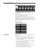
AC Induction Motors Typical Cutaway View of a Dripproof, Horizontal Integral Horsepower Motor 364 - 445 Frame Size Item 1. 2. 3. 4. 5. 6. 7. 8. 9. 10. Description Frame Vent Screen 1 Conduit Box Bottom Conduit Box Top-Holding Screw Conduit Box Top Conduit Box Bottom-Holding Bolt Ball Bearing O.P.E. 2 Pre-loading Spring Inner Bearing Cap O.P.E. Grease Plug Inner Bearing Cap Bolt Item 11. 12. 13. 14. 15. 16. 17. 18. 19. 20. Description Bracket O.P.E. Baffle Plate O.P.E.
Notes AC Induction Motors
AC Induction Motors Notes 15
Online Documentation The latest motor information can be obtained from the Allen-Bradley Drives & Motors home page on the World Wide Web at: http://www.controlmatched.com Publication 1329M-UM001B-EN-P – August, 2001 Supersedes 1329M-UM001A-US-P dated April, 2000 Copyright © 2001 Rockwell Automation. All rights reserved. Printed in USA.