Installation, Operation and Maintenance Manual AC Induction Motors • Frames L180 - L440 • Specifically designed for use with Adjustable Frequency AC Drives
AC Induction Motors General Description The motors described in this publication are high performance motors specifically designed for use with adjustable frequency drives. The basic design includes Class H insulation, 1.0 service factor, 40 degree C ambient, continuous duty. Standard enclosures are totally enclosed blower cooled, totally enclosed fan-cooled, non-ventilated and dripproof force ventilated. Modifications and accessories are available.
AC Induction Motors Receiving and Handling 3 Acceptance Thoroughly inspect this equipment before accepting shipment from the transportation company. If any of the goods called for in the bill of lading or express receipt are damaged or the quantity is short, do not accept them until the freight or express agent makes an appropriate notation on your freight bill or express receipt.
AC Induction Motors Storage Motors must be stored in a clean, dry area protected from extremes of temperature, moisture, shock and vibration. Storage temperatures of 10 to 49 degrees C (50 to 120 degrees F) with a maximum relative humidity of 60% must be observed. In addition, motors subjected to extended storage must be handled and treated per the requirements specified in publication “Motors-5.0.” This publication is available from your Allen-Bradley Sales Office or online at: http://www.
AC Induction Motors 5 Drain Plugs If motor is totally enclosed, it is recommended that condensation drain plugs be removed. These are located in the lower portion of the end-shields (not included on L180 frames). Totally enclosed “XT” motors are equipped with automatic drains which should be left in place as received. Power Supply This is an adjustable speed motor designed for operation with adjustable frequency drives.
AC Induction Motors Coupled Drive Motors will operate successfully mounted on the floor, wall or ceiling, and with the shaft at any angle from horizontal to vertical. Special mountings, duty or thrust demands may, however, require a different bearing system. ! ATTENTION: Motor C-face is intended for mounting auxiliary equipment such as pumps and gears. When mounted horizontally, C-face motors should be supported by the feet and not by the C-face.
AC Induction Motors 7 Connections ! ! ATTENTION: The user is responsible for conforming with the National Electrical Code and all other applicable local codes. Wiring practices, grounding, disconnects and overcurrent protection are of particular importance. Failure to observe these precautions could result in severe bodily injury or loss of life. ATTENTION: This equipment is at line voltage when AC power is connected. Disconnect and lockout all ungrounded conductors of the power line.
AC Induction Motors Direction of Rotation These motors are capable of bi-directional shaft rotation. When voltages in an A-B-C phase sequence are applied to leads U/T1, V/ T2, W/T3, clockwise shaft rotation facing the opposite drive end will result. If shaft rotation is incorrect, change the direction of rotation as follows: ! 1. ATTENTION: The drive may apply hazardous voltages to the motor leads after drive power has been removed.
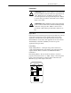
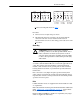
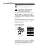
AC Induction Motors (Delta) T6 T4 T1 T2 L1 L2 Low Volts (Star) T5 T6 T3 T4 T1 L3 L1 Line T2 9 (Delta) W2 T5 T3 L2 L3 High Volts or U1 U2 V1 L1 L2 Low Volts U1 = Black U2 = Green (Star) V2 W2 W1 U2 U1 L3 L1 Line V1 = Blue V2 = White V1 V2 W1 L2 L3 High Volts W1 = Brown W2 = Yellow or Connection Diagram shown on page 7. Procedure: 1. Connect for low or high voltage as shown. 2.
AC Induction Motors ! ! ATTENTION: Incorrect motor rotation may cause personal injury or damage the equipment. Check direction of motor rotation before coupling motor to load. ATTENTION: Ensure that all guards are properly installed before proceeding. Exercise extreme care to avoid contacting rotating parts. Failure to observe these precautions could result in personal injury. Proper alignment is a key step for long life of bearings, shafts and belts, and minimum downtime.
AC Induction Motors 11 Epic Connector or Plain Cable Connections Pin 1 2 3 4 5 Motor Application Data Signal Common B A Z No Connection Color Black Green Blue Violet – Pin 6 7 8 9 10 Signal 5-15V B (NOT) A (NOT) Z (NOT) Shield Color Red Yellow Gray Orange Braid Maximum Safe Speed ! ATTENTION: The machinery builder and/or user are responsible for assuring that all drive train mechanisms, the driven machine, and process material are capable of safe operation at the maximum speed at which the machin
AC Induction Motors Minimum V-Belt Sheave Diameters Application of Pulleys, Sheaves, Sprockets and Gears on Motor Shafts To avoid excessive bearing loads and shaft stresses, belts should not be tightened more than necessary to transmit the rated torque. The pre-tensioning of the V-belt drive should be based on the total tightening force required to transmit the horsepower divided by the number of belts.
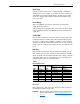
AC Induction Motors 13 Table C Constants for Calculating the Minimum Sheave Diameters for V-Belt Drives Frame L210 L250 L280 L320 UL360 UL400 Units inches “V” Dimension 3.50 millimeters 88.9 inches 4.00 millimeters 101.6 inches 4.50 millimeters 114.3 inches 5.00 millimeters 127.0 inches 6.25 millimeters 158.8 inches 8.00 millimeters 203.2 Constant A B C D A B C D A B C D A B C D A B C D A B C D Base RPM 850 1150 40.6 30.0 7.26 5.43 1384 1022 9.73 7.28 23.33 18.25 3.58 2.
AC Induction Motors ! ATTENTION: The use of these radial load capacities requires the accurate calculation of the radial load for the application. Radial loads for gears, sprockets, and flywheel are usually accurately determined but the radial loads due to V-belt drives are subject to miscalculations because they do not include all of the pre-tension load (belt tightening).
AC Induction Motors 15 In addition to observing the above precaution, all precautions (Attentions) mentioned previously in this document should be observed. • Stop and remove power from the motor per the Drive User Manual directions. • Verify that the DC bus voltage is zero per the Drive User Manual. • The interior of the motor should be clean and dry. • Connections must be tight. • The driven machine should be unloaded, if possible.
AC Induction Motors Maintenance ! ATTENTION: Internal parts of this motor may be at line potential even when it is not rotating. Before performing any maintenance which could result in contacting any internal part, be sure to disconnect all power from the motor. Failure to observe this precaution could result in severe personal injury or death. Amount of grease to be added to motors is shown in Table F. See Table H for relubrication interval.
AC Induction Motors 17 Table H Relubrication Periods - Frames L180 - L440 Maximum Normal Operating Speed (RPM) 1 Frame 3450 and higher All 2400 - 3449 L180 - L250 L280 - L440 1700 - 2399 L180 - L320 L360 - L440 UL360 - UL440 800 - 1699 L180 - L320 L360 - L440 UL360 - UL440 500 - 799 L180 - L320 L360 - L440 UL360 - UL440 499 and lower L180 - L440 UL360 - UL440 1 2 Relubrication Interval (Months) Standard Severe Extreme Service Service Service 9 4 1 24 9 3 9 3 1 36 12 3 18 6 2 9 3 1 36 24 8 36 12 3 9 6 1 4
AC Induction Motors Use Chevron SRI-2 grease or equivalent unless motor nameplate specifies special grease. Use only clean, fresh grease from clean containers and handle carefully to keep it clean. In general, mixing of greases is not recommended. If an incompatible grease is used, the lube system must be repacked completely with the new grease. 5. Wipe away any excess grease at the grease drain or relief and replace drain plugs.
AC Induction Motors 19 Frequent bearing checks are recommended. If temperatures become excessive, investigate immediately for the cause. Total bearing temperatures should not exceed 121 degrees C (250 degrees F). Causes for high bearing temperature are: • Contaminated grease. • Insufficient grease or excessive amount. • Incorrect grease. • Excessive load or thrust due to misalignment or motor overload. • Loose bearings. • Bearing failure. • Excessive ambient temperature.
AC Induction Motors Bearing Replacement Remove bearing by means of bearing puller. Clean bearing housing and bearing seat prior to assembly of bearing. Place new bearing in a bake oven for 1/2 hour at 121 degrees C (250 degrees F). Place bearing onto shaft and push home to bearing shoulder. Hold it in place for a minimum of 30 seconds. After bearing has cooled down for about 1 minute, add 1/2 cu. in. of fresh grease into back of bearing.
AC Induction Motors 21 Screw-in Stub Shaft 1. Turn off and lockout power to the motor. 2. Remove in-line blower motor and cover assembly by removing the hex head cap screws on cover (if enclosure is TEAO-Blower cooled). 3. After removal of blower assembly, motor shaft will need to be locked from turning. The use of a spanner wrench on motor drive shaft or alternate means can be used. Place an open-end wrench on stub shaft flats and turn counter clockwise (right-hand threads). 4.
AC Induction Motors Parts Identification Drawing Totally Enclosed Blower Cooled Item No. 1 2 3 4 5 6 7 8 9 10 11 12 Total Service Programs Part Description Frame/stator Rotor Bracket, B.E. Bracket, F.E. Shaft Ball Bearing, B.E. Inner Cap, B.E. Ball Bearing, F.E. Inner Cap, F.E. Wave Washer, B.E. Blower Motor Cover, Blower Item No. 13 14 15 16 17 18 19 20 21 22 23 Part Description Grill, Blower Eyebolt Conduit Box, Main Motor Grease Fitting, B.E. Grease Fitting, F.E.
AC Induction Motors Notes 23
Online Documentation The latest motor information can be obtained from the Allen-Bradley Drives & Motors home page on the World Wide Web at: http://www.controlmatched.com Publication 1329L-UM001A-EN-P – July, 2001 Supersedes 1329L-5.0 dated March, 2000 Copyright © 2001 Rockwell Automation. All rights reserved. Printed in USA.