
User Manual


1329I-5.0 Integrated Drive/Motor — January, 1999
Appendix
D
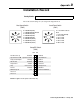
Installation Record
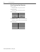
Record the switch settings for your setup in the diagrams below.
Catalog Number:
0 = 1 Second Accel/5 Sec
Decel
1 = 5 Seconds (Default)
2 = 10 Seconds
3 = 15 Seconds
4 = 20 Seconds
5 = 30 Seconds
6 = 60 Seconds
0 = 1500 RPM (50 Hz)
1 = 1800 RPM (60 Hz) Default
2 = 2100 RPM (70 Hz)
3 = 2400 RPM (80 Hz)
4 = 2700 RPM (90 Hz)
5 = 3000 RPM (100 Hz)
6 = 3300 RPM (110 Hz)
7 = 3600 RPM (120 Hz)
OFF ON
Enabled
Terminal Block
Faulted
Enabled
Constant
Ramp-to-Rest
Disabled
From Terminal Block
Run On Power Up
Speed Reference ➊
Relay Control Output
Auto Restart
Torque Curve
Stop
Reverse
Minimum Speed
Not Used
Not Used
Disabled
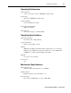
Operator Controls
Running
Disabled
Variable
Coast-to-Rest
Enabled
3 Hz
Max Speed Switch
(SW2)
Accel/Decel Switch
(SW1)
Setup DIP Switch
(SW3)
➊ Switch 2 applies to local operator control units only.