
User Manual

Checklist-2
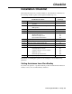
Installation Checklist
1329I-5.0 Integrated Drive/Motor — January, 1999
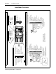
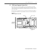
Installation Overview
Accel / Decel Switch
Max Speed Switch
Setup DIP Switch
Top View of Unit
With Cover Removed
Display Board
- DBR (Do Not Wire)
Connections
AC Input Power
DC Bus (Do Not Wire)
AC Inputs
➋
12 RPM / %Load Display
10 Speed Preset 0
11 Function Loss
13 24V DC
14 Forward/Reverse
15 Reset
16 Start
18 24 DC Common
19 N.O. Relay
20 Relay Common
=
N.O. Momentary Contact
=
Maintained Contact - Open
=
Maintained Contact - Closed
=
N.C. Momentary Contact
Maintained 2-Wire
➊
Start
17
16
%LOAD
RPM
13
REV
+ -
FWD
➋
5K
9 Speed Preset 1
5 0 to 10V Output
7 24V DC
8 Speed Preset 2
2 0 to 10V Spd Ref Input
3 4 to 20 mA Spd Ref Input
+10VDC
1 10 Volt Reference
Ground
Momentary 3-Wire
Start
Min Spd from Terminal Block Inputs
= Default Setting (OFF Position)
3 Hz Minimum Speed
Reverse Enabled
Coast-to-Rest Stop
867
Analog Spd Ref from Terminal Block
➊
Spd Ref from Operator Controls
Relay Output Control: Running
Run On Power Up Disabled
Variable Torque Curve
Auto Restart Disabled
4532
N
1
O
910
(Not Used)
(Not Used)
➊
RPM
%LOAD
+ -
Local Operator Control Unit
Standard Unit
(0 to Max Spd)
0 = 1 sec accel / 5 sec decel
1 = 5 sec (Default)
2 = 10 sec
3 = 15 sec
4 = 20 sec
5 = 30 sec
6 = 60 sec
7 = 90 sec
6
2
3
4
5
1
0
7
Connector
➊
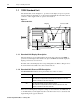
Slide switch 2 is used only with local operator control units.
Connect to external
device such as PLC
input.
input
.
Connect to external
device such as PLC
3
4
5
1
2
7
0
6
0 = 1500 RPM (50 Hz)
7 = 3600 RPM (120 Hz)
6 = 3300 RPM (110 Hz)
5 = 3000 RPM (100 Hz)
4 = 2700 RPM (90 Hz)
3 = 2400 RPM (80 Hz)
2 = 2100 RPM (70 Hz)
1 = 1800 RPM (60 Hz) (Default)
Run On Power Up Enabled
Relay Output Control: Faulted
Auto Restart Enabled
Constant Torque Curve
Ramp-to-Rest Stop
Reverse Disabled (Reverse Lockout)
6 Common
➊
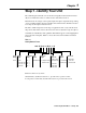
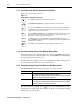
Control Signal Terminal Block Connections
Common4
12 RPM / %Load Display
10 Speed Preset 0
11 Function Loss
13 24V DC
14 Forward/Reverse
15 Reset
16 Start
18 24 DC Common
19 N.O. Relay
20 Relay Common
9 Speed Preset 1
5 0 to 10V Output
7 24V DC
8 Speed Preset 2
2 0 to 10V Spd Ref Input
3 4 to 20 mA Spd Ref Input
1 10 Volt Reference
6 Common
Common4
Stop17
Stop17
➊
Selectors and Connectors
The jumper between terminals 7 and 11
must be removed when wiring the
Function Loss input. See Section 7.1
for more information.
An external 0 to 10 volt or 4 to 20 mA
speed reference source can be connected.
See Section 7.5.3 for more infomation.
The jumper between terminals 7 and 11
must be removed when wiring the
Function Loss input. See Section 7.1
for more information.