
User Manual

Step 7 - Wire the Control Signal Terminal Block
7-7
1329I-5.0 Integrated Drive/Motor — January, 1999
Select the option that is the most suitable for your application. The following sections
provide wiring information for each option except the local operator controls. Refer to
Section 1.2 for information on the local operator controls.
7.5.1 Wiring the Preset Speed Inputs
Control terminals 8, 9, and 10 select seven preset speeds as shown in Table 7.4. Note
that if you select a preset speed that is greater than the maximum speed setting (based
on the rotary switch setting), the unit uses the maximum speed setting value.
Important:
DIP switch position 8 defines whether terminals 8, 9, and 10 are used as
presets (default) or to define the unit’s minimum speed (user option).
Refer to Section 8.3.8 for information about using terminals 8, 9, and 10
to select minimum speed.
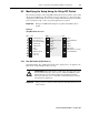
Table 7.4
Fixed Preset Speed Selections
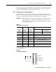
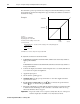
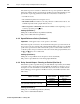
To use the preset speeds to set the speed reference, wire to terminals 8, 9, and 10 as
shown in Figure 7.8.
Figure 7.8
Preset Speed Input Wiring
Selected Speed Reference
Terminal 8
Status
Terminal 9
Status
Terminal 10
Status
Standard Unit Local Operator
Control Unit
Open Open Open Analog speed reference Local operator control
Open Open Closed Preset 1 - 300 RPM (10 Hz)
Open Closed Open Preset 2 - 600 RPM (20 Hz)
Open Closed Closed Preset 3 - 900 RPM (30 Hz)
Closed Open Open Preset 4 - 1200 RPM (40 Hz)
Closed Open Closed Preset 5 - 1500 RPM (50 Hz)
Closed Closed Open Preset 6 - 1800 RPM (60 Hz)
Closed Closed Closed Preset 7 - 2100 RPM (70 Hz)
687 9 10 11
24 Volt DC
Speed Preset 2
Speed Preset 1
Speed Preset 0