
User Manual

1329I-5.0 Integrated Drive/Motor — January, 1999
Table of Contents
Installation Checklist
Chapter 1 Step 1 - Identify Your Unit
1.1 1329I Standard Unit . . . . . . . . . . . . . . . . . . . . . . . . . . . . . . . . . . . . . . . . . . 1-2
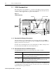
1.1.1 Standard Unit Display Description . . . . . . . . . . . . . . . . . . . . . . . . . 1-2
1.1.2 Standard Unit Reverse LED Description . . . . . . . . . . . . . . . . . . . . 1-2
1.2 1329I Local Operator Control Unit . . . . . . . . . . . . . . . . . . . . . . . . . . . . . . . 1-3
1.2.1 Local Operator Control Unit Key Descriptions . . . . . . . . . . . . . . . . 1-4
1.2.2 Local Operating Control Unit Display Description . . . . . . . . . . . . . 1-4
1.2.3 Local Operating Control Unit Reverse LED Description . . . . . . . . . 1-4
1.2.4 Operating the Unit Using the Local Operator Controls . . . . . . . . . . 1-5
Chapter 2 Step 2 - Plan the Installation
2.1 Wire Routing Guidelines . . . . . . . . . . . . . . . . . . . . . . . . . . . . . . . . . . . . . . . 2-3
2.2 Handling and Lifting Guidelines . . . . . . . . . . . . . . . . . . . . . . . . . . . . . . . . . 2-4
Chapter 3 Step 3 - Mount the Unit
3.1 Mounting Guidelines for Face-Mounted Motors . . . . . . . . . . . . . . . . . . . . . 3-1
3.2 Mounting Dimensions for NEMA Frames . . . . . . . . . . . . . . . . . . . . . . . . . . 3-2
Chapter 4 Step 4 - Install External Power Components
4.1 Installing an AC Input Disconnect . . . . . . . . . . . . . . . . . . . . . . . . . . . . . . . . 4-1
4.2 Installing Branch Circuit Protection . . . . . . . . . . . . . . . . . . . . . . . . . . . . . . . 4-1
4.3 Installing Input Isolation Transformers . . . . . . . . . . . . . . . . . . . . . . . . . . . . 4-2
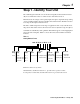
Chapter 5 Step 5 - Wire AC Power to the Unit and Ground the Unit
5.1 Grounding the Unit . . . . . . . . . . . . . . . . . . . . . . . . . . . . . . . . . . . . . . . . . . . 5-2
Chapter 6 Step 6 - Install a Hardwired Stop
Chapter 7 Step 7 - Wire the Control Signal Terminal Block
7.1 Wiring Function Loss . . . . . . . . . . . . . . . . . . . . . . . . . . . . . . . . . . . . . . . . . 7-5
7.2 Wiring the Analog Output . . . . . . . . . . . . . . . . . . . . . . . . . . . . . . . . . . . . . . 7-5
7.3 Wiring the Relay Control Output . . . . . . . . . . . . . . . . . . . . . . . . . . . . . . . . . 7-6
7.4 Wiring RPM or Percent Load Display . . . . . . . . . . . . . . . . . . . . . . . . . . . . . 7-6
7.5 Wiring the Speed Reference . . . . . . . . . . . . . . . . . . . . . . . . . . . . . . . . . . . . 7-6
7.5.1 Wiring the Preset Speed Inputs . . . . . . . . . . . . . . . . . . . . . . . . . . . 7-7
7.5.2 Wiring the Speed Reference Signal Potentiometer . . . . . . . . . . . . 7-8
7.5.3 Wiring an External Speed Reference . . . . . . . . . . . . . . . . . . . . . . . 7-8
7.6 Wiring Start / Stop Control . . . . . . . . . . . . . . . . . . . . . . . . . . . . . . . . . . . . . 7-9
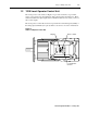
7.7 Wiring Forward / Reverse Control . . . . . . . . . . . . . . . . . . . . . . . . . . . . . . . 7-10
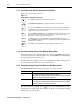
7.8 Wiring Reset Control . . . . . . . . . . . . . . . . . . . . . . . . . . . . . . . . . . . . . . . . . . 7-10