
User Manual


7-4
Step 7 - Wire the Control Signal Terminal Block
1329I-5.0 Integrated Drive/Motor — January, 1999
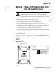
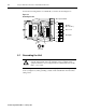
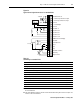
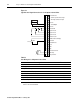
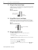
Figure 7.3
Typical Control Signal Connections for Local Operator Control Units
Table 7.3
User Wiring for Local Operator Control Units
➊
The jumper between terminals 7 and 11 must be removed when wiring the Function Loss input. See
Section 7.1 for more information.
Signal Refer to Section
Function Loss
7.1
Analog Input
7.2
Relay Control Output
7.3
RPM/Percent Load Display
7.4
Speed Reference (select one)
Preset Speed
7.5.1
Speed Potentiometer
7.5.2
External Speed Reference (0 – 10V DC or 4 – 20 mA)
7.5.3
1234567891011121314151617181920
10 Volt Reference
0 – 10V DC Speed Reference Inpu
t
4 – 20 mA Speed Reference Input
Common
0 – 10 Volt Output
Common
Speed Preset 2
Speed Preset 1
Speed Preset 0
Forward/Reverse
24 Volt DC
RPM/Percent Load Display
Reset
Start
Stop
24 Volt DC Common
N.O. Relay
Relay Common
24 Volt DC ➊
Function Loss ➊
-+
RPM
% Load