
User Manual


3-2
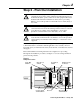
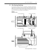
Step 3 - Mount the Unit
1329I-5.0 Integrated Drive/Motor — January, 1999
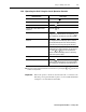
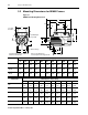
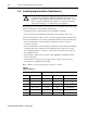
3.2 Mounting Dimensions for NEMA Frames
Figure 3.1
NEMA Frame Mounting Dimensions
Frame Size Dimensions in inches (mm)
A2EH DBFAJAKUAHSES
56C
6.71
(170)
5.50
(140)
0.34
(8.6)
3.50
(89)
3/8-16 5.88
(149)
4.50
(114)
0.625
(15.9)
2.06
(52)
.19 SQ
(4.8)
1.25
(32)
143TC
145TC
6.71
(170)
5.50
(140)
0.34
(8.6)
3.50
(89)
3/8-16 5.88
(149)
4.50
(114)
0.875
(22.3)
2.12
(54)
.19 SQ
(4.8)
1.25
(32)
182TC
184TC
8.50
(216)
7.50
(191)
0.34
(8.6)
4.50
(114)
1/2-13 7.25
(184)
8.50
(216)
1.125
(28.6)
2.62
(67)
.25 SQ
(6.4)
1.50
(38)
Frame Size Dimensions in inches (mm)
BC BB BA B 2F 1 2F 2 EV C P BV
56C
0.19
(4.8)
0.12
(3.0)
2.75
(70)
6.50
(165)
3.00
(76)
5.00
(127)
0.47
(12)
15.90
(404)
8.38
(213)
10.14
(258)
143TC
0.12
(3.0)
0.12
(3.0)
2.75
(70)
6.50
(165)
4.00
(102)
5.00
(127)
0.47
(12)
16.46
(418)
8.38
(213)
10.14
(258)
145TC
0.12
(3.0)
0.12
(3.0)
2.75
(70)
6.50
(165)
4.00
(102)
5.00
(127)
0.47
(12)
15.96
(405)
8.38
(213)
10.64
(270)
182TC
0.12
(3.0)
0.25
(6.4)
3.50
(89)
6.50
(165)
4.50
(114)
5.50
(140)
0.50
(13)
18.75
(476)
8.80
(224)
12.39
(315)
184TC
0.12
(3.0)
0.25
(6.4)
3.50
(89)
6.50
(165)
4.50
(114)
5.50
(140)
0.50
(13)
19.75
(502)
8.80
(224)
13.39
(340)
45
D
2E
A
P
AJ
BF
H - Diameter Through
Face Runout and Eccentricity .004 Max. T.I.R.
Shaft Runout .002 Max. T.I.R.
S - Key Width/Height
ES - Key Length
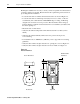
3/4 Conduit
Both Sides
* Denotes Control Wiring Ports
** Denotes Input Power Port Opposite Side
B
C
BB
BV
6.00
AK
BA
2F 1
2F 2
EV
4.50
BC
AH
U
**
.75
8.01
*