329I Integrated Drive/Motor 1.0-5.
Important User Information Because of the variety of uses for the products described in this publication, those responsible for the application and use of this control equipment must satisfy themselves that all necessary steps have been taken to assure that each application and use meets all performance and safety requirements, including any applicable laws, regulations, codes and standards.
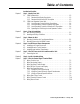
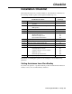
Table of Contents Installation Checklist Chapter 1 Step 1 - Identify Your Unit 1.1 1329I Standard Unit . . . . . . . . . . . . . . . . . . . . . . . . . . . . . . . . . . . . . . . . . . 1-2 1.1.1 Standard Unit Display Description . . . . . . . . . . . . . . . . . . . . . . . . . 1-2 1.1.2 Standard Unit Reverse LED Description . . . . . . . . . . . . . . . . . . . . 1-2 1.2 1329I Local Operator Control Unit . . . . . . . . . . . . . . . . . . . . . . . . . . . . . . . 1-3 1.2.
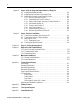
ii Chapter 8 Step 8 -Verify the Setup and Adjust Switches if Required 8.1 Adjusting the Maximum Speed . . . . . . . . . . . . . . . . . . . . . . . . . . . . . . . . . . 8-2 8.2 Adjusting the Acceleration / Deceleration Time . . . . . . . . . . . . . . . . . . . . . . 8-3 8.3 Modifying the Setup Using the Setup DIP Switch . . . . . . . . . . . . . . . . . . . . 8-5 8.3.1 Run On Power Up (Position 1) . . . . . . . . . . . . . . . . . . . . . . . . . . . . 8-5 8.3.2 Speed Reference Select (Position 2) . . .
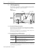
Checklist Installation Checklist This manual describes how to install, troubleshoot, and maintain the 1329I unit. Use the following checklist to guide you through the installation process. Read Manual Section(s) Installation Procedure ❑ Step 1 Identify your unit 1.0 Understand how the standard unit operates 1.1 Understand how the local operator control unit operates 1.2 ❑ Step 2 Plan the installation 2.0 ❑ Step 3 Mount the unit 3.
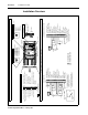
Relay Output Control: Faulted Auto Restart Enabled Constant Torque Curve Ramp-to-Rest Stop Reverse Disabled (Reverse Lockout) Min Spd from Terminal Block Inputs (Not Used) 2 3 4 5 6 7 8 9 10 Relay Output Control: Running Auto Restart Disabled Variable Torque Curve Coast-to-Rest Stop Reverse Enabled 3 Hz Minimum Speed RPM Start Maintained 2-Wire Momentary 3-Wire Start %LOAD ➊ 16 17 13 REV 9 Speed Preset 1 10 Speed Preset 0 11 Function Loss 12 RPM / %Load Display 13 24V DC 14 Forward/R
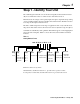
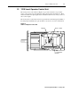
Chapter 1 Step 1 - Identify Your Unit The 1329I integrated drive/motor is an AC drive integrally mounted with an inverter duty motor. Each unit consists of a Drive Section and a Motor Section. The Drive Section is a single- or three-phase input, three-phase output inverter providing open loop V/Hz regulation. It houses the PC boards and the blower. The Motor Section is a four-pole, three-phase induction motor. The unit’s default setup suits a wide range of applications.
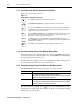
1-2 Step 1 - Identify Your Unit 1.1 1329I Standard Unit The standard unit, shown in Figure 1.1, provides a local display for speed or percent load, and diagnostic information. A control signal terminal block in the Drive Section connects to a user-supplied remote operator control station. Figure 1.1 1329I Standard Unit Display Reverse LED Drive Section Motor Section 1.1.
Step 1 - Identify Your Unit 1329I Local Operator Control Unit The local operator control unit (see Figure 1.2) provides local start, stop, forward, reverse, reset, and speed control functions. The controls replace the Start, Stop, Reset, and Forward / Reverse input signals at the terminal block. For local control, you do not wire to these inputs The local operator control unit receives its speed reference from the keypad (default) or the analog input terminals (user option). Refer to Section 8.3.
1-4 Step 1 - Identify Your Unit 1.2.1 Local Operator Control Unit Key Descriptions Figure 1.3 shows each key’s function. Figure 1.3 Local Operator Control Key Functions The START key applies power to the Motor Section. The FORWARD/REVERSE key toggles the direction of motor rotation. Press the UP ARROW key once to display the current speed reference. Hold this key down to increase the speed reference value. The longer the key is pressed, the faster the reference value increases.
Step 1 - Identify Your Unit 1-5 1.2.4 Operating the Unit Using the Local Operator Controls Desired Action User Steps Start the unit. Press the green key. Stop the unit. Press the red Change the direction of motor rotation. Press the Clear faults or abort Auto Restart sequence. Press the Decrease the speed reference. ➊ Press the key until the speed reference displayed is the desired value. The longer the key is held down, the faster the value decreases.
1-6 Step 1 - Identify Your Unit End of Chapter 1329I-5.
Chapter 2 Step 2 - Plan the Installation ATTENTION: Only qualified electrical personnel, familiar with the construction and operation of this equipment and the hazards involved, should install, adjust, operate, and/or service this equipment. Read and understand this instruction manual in its entirety before proceeding. Failure to observe this precaution could result in severe bodily injury or loss of life. ATTENTION: This equipment is at line voltage when AC power is connected.
2-2 Step 2 - Plan the Installation Planning the installation is necessary to ensure you have acceptable environmental and operating conditions for the unit. Read and follow the requirements given below before proceeding with the installation: • Locate the unit where it will have unrestricted clearance as shown in Figure 2.2. • Locate the unit where it will be kept clean (away from oil, coolants, or airborne contaminants). The 1329I unit has an IP54/NEMA Type 12 rating.
Step 2 - Plan the Installation 2.1 2-3 Wire Routing Guidelines The 1329I unit is shipped from the factory with plastic conduit plugs installed. These plugs must be removed. Before wiring, replace these plugs with appropriate 3/4-inch NPT connectors having a similar enclosure rating. After wiring, seal unused routing holes using permanent, user-supplied 3/4-inch NPT plugs. Seal all threaded connections. Route the power and control wiring as shown in Figure 2.3. Figure 2.
2-4 Step 2 - Plan the Installation 2.2 Handling and Lifting Guidelines Follow these handling and lifting guidelines: • In the case of assemblies on a common base, carefully lift the assembly by a sling around the base or by other lifting means on the base. • When designing the lifting means, take care to assure lifting in the intended direction. • Do not lift the unit by the plastic blower cover. • Do not use any lifting means under the Drive Section.
Chapter 3 Step 3 - Mount the Unit Mount the unit on a foundation sufficiently rigid to guard against excessive vibration. The unit may be mounted at any orientation. After carefully aligning the 1329I unit with the driven machinery, bolt securely in place. When the unit is mounted vertically, it may be necessary to use additional guards to prevent foreign objects from falling into the motor fan openings and striking rotating parts. Mounting dimensions are provided on the following pages of this chapter.
Step 3 - Mount the Unit 3-2 3.2 Mounting Dimensions for NEMA Frames Figure 3.1 NEMA Frame Mounting Dimensions C BV 6.00 * AH ** .75 BB P 3/4 Conduit Both Sides BF AJ S - Key Width/Height ES - Key Length 45 8.01 4.50 AK D U BC 2E BA H - Diameter Through 2F 1 EV A Face Runout and Eccentricity .004 Max. T.I.R. Shaft Runout .002 Max. T.I.R.
Chapter 4 Step 4 - Install External Power Components Install external power components using the guidelines in the following sections. 4.1 Installing an AC Input Disconnect ATTENTION: Local codes and laws require that an input disconnect be provided in the incoming power lines. Failure to observe this precaution could result in severe bodily injury or loss of life. An AC input disconnect must be provided in the incoming AC power lines in accordance with local codes and laws. 4.
4-2 Step 4 - Install External Power Components 4.3 Installing Input Isolation Transformers ATTENTION: Distribution system capacity above the maximum recommended system KVA (100 KVA for 460 VAC three-phase, 5% impedance) requires using an isolation transformer, a line reactor, or other means of adding similar impedance. Failure to observe this precaution could result in damage to, or destruction of, the equipment.
Chapter 5 Step 5 - Wire AC Power to the Unit and Ground the Unit ATTENTION: If the distribution system capacity exceeds the unit’s maximum symmetrical fault short-circuit current of 10,000 amps, additional impedance should be added to the AC line supplying the unit to limit available current in the event of a fault. Failure to observe this precaution could result in severe bodily injury or loss of life. Observe the following guidelines when wiring AC power: • The terminal block accepts up to 3.
5-2 Step 5 - Wire AC Power to the Unit and Ground the Unit Connect the incoming AC line to terminals R, S, and T, as shown in Figure 5.2. Figure 5.2 Grounding the Unit AC Input Terminal DC+ DC- DC Bus (Do not wire.) DC+ DC- DBR Not Used DBR PE T/L3 S/L2 T/L3 R/L1 S/L2 AC Inputs R/L1 PE Ground 5.1 Grounding the Unit ATTENTION: The user is responsible for conforming with all local, national, and international codes applicable to the grounding of this equipment.
Chapter 6 Step 6 - Install a Hardwired Stop ATTENTION: The user must provide an external, hardwired stop circuit outside of the 1329I unit circuitry. This circuit must disable the system in case of improper operation. Uncontrolled machine operation may result if this procedure is not followed. Failure to observe this precaution could result in bodily injury.
6-2 Step 6 - Install a Hardwired Stop End of Chapter 1329I-5.
Chapter 7 Step 7 - Wire the Control Signal Terminal Block The following sections describe how to wire the control signal terminal block shown in Figure 7.1. Refer to either Figure 7.2 (standard units) or Figure 7.3 (local operator control units) before you begin wiring. These figures show typical wiring connections and the sections in this chapter where the signals are described in detail. Note the following when wiring the terminal block: • The terminal block is isolated from the input power.
7-2 Step 7 - Wire the Control Signal Terminal Block Figure 7.1 Control Signal Terminal Block 1 2 3 4 5 6 7 8 9 10 11 12 13 14 15 16 17 18 19 20 Table 7.
Step 7 - Wire the Control Signal Terminal Block 7-3 Figure 7.2 Typical Control Signal Connections for Standard Units - RPM % Load 5K Ω + Fwd Rev 1 2 3 4 5 6 7 8 9 10 11 12 13 14 15 16 17 18 19 20 +10V DC 10 Volt Reference ➊ 0 – 10V DC Speed Reference Input 4 – 20 mA Speed Reference Input Common 0 – 10 Volt Output Common 24 Volt DC ➋ Speed Preset 2 Speed Preset 1 Speed Preset 0 Function Loss ➋ RPM/Percent Load Display 24 Volt DC Forward/Reverse Reset Start Stop 24 Volt DC Common N.O.
7-4 Step 7 - Wire the Control Signal Terminal Block Figure 7.3 Typical Control Signal Connections for Local Operator Control Units RPM % Load 3 4 5 6 7 8 9 10 11 12 13 14 15 16 17 18 19 20 + 1 2 - 10 Volt Reference 4 – 20 mA Speed Reference Input 0 – 10V DC Speed Reference Input Common 0 – 10 Volt Output Common 24 Volt DC ➊ Speed Preset 2 Speed Preset 1 Speed Preset 0 Function Loss ➊ RPM/Percent Load Display 24 Volt DC Forward/Reverse Reset Start Stop 24 Volt DC Common N.O.
Step 7 - Wire the Control Signal Terminal Block 7.1 7-5 Wiring Function Loss For the unit to run, you must maintain a signal at the Function Loss input (the connection between control terminals 7 and 11). If the Function Loss signal is not present, the unit turns off the power devices and coasts to rest. To restart the unit, you must restore the Function Loss signal, clear any faults, and reassert the Start command.
7-6 Step 7 - Wire the Control Signal Terminal Block 7.3 Wiring the Relay Control Output A single form A relay on the terminal block can be used to indicate the unit is running (default) or has faulted (user option) based on the setup DIP switch setting. Refer to the setup DIP switch description in Chapter 8. Figure 7.6 Relay Control Output Wiring 7.4 17 18 19 20 Connect to external device such as PLC input. N.O.
Step 7 - Wire the Control Signal Terminal Block 7-7 Select the option that is the most suitable for your application. The following sections provide wiring information for each option except the local operator controls. Refer to Section 1.2 for information on the local operator controls. 7.5.1 Wiring the Preset Speed Inputs Control terminals 8, 9, and 10 select seven preset speeds as shown in Table 7.4.
7-8 Step 7 - Wire the Control Signal Terminal Block 7.5.2 Wiring the Speed Reference Signal Potentiometer Control terminal 1 provides a 10 VDC reference for use with the user-supplied 5 kΩ potentiometer. Perform the following procedure to wire the potentiometer as the speed reference (refer to Figure 7.9): 1. Mount the speed reference potentiometer at an appropriate operator-accessible location, less than 300 meters (1000 feet) from the 1329I unit. 2.
Step 7 - Wire the Control Signal Terminal Block 7-9 4 to 20 mA External Speed Reference To use an external 4 to 20 mA signal to set the speed reference, connect the signal leads as shown in Figure 7.11. 4 to 20 mA = 0 to maximum speed. Figure 7.11 4 to 20 mA External Speed Reference Wiring 1 2 3 4 5 Shield 4 – 20 mA Speed Reference Input Common (Drive end only) 7.6 Wiring Start / Stop Control Important: This applies to standard units only.
7-10 Step 7 - Wire the Control Signal Terminal Block 7.7 Wiring Forward / Reverse Control Important: This applies to standard units only. The Forward / Reverse input (the connection between terminals 13 and 14) defines the requested direction of motor rotation. If the input is open, the requested direction is forward. Switching the Forward / Reverse input causes the motor to ramp to rest and then accelerate in the opposite direction.
Chapter 8 Step 8 - Verify the Setup and Adjust Switches if Required The 1329I unit is set up using two rotary switches and a 10-position DIP switch mounted on the printed circuit board as shown in Figure 8.1. Figure 8.1 shows the setting selections and the factory defaults. Normally, no adjustments will be needed to the factory settings. If your application requires adjustment to these settings, refer to the following sections in this chapter.
8-2 Step 8 - Verify the Setup and Adjust Switches if Required Figure 8.1 Rotary Switches and Setup DIP Switch Locations Setup DIP Switch (SW3) OFF ON Max Speed Switch (SW2) Accel/Decel Switch (SW1) DC+ DCDBR PE T/L3 S/L2 R/L1 8.1 Adjusting the Maximum Speed ATTENTION: The user is responsible for ensuring that driven machinery and all drive-train mechanisms are capable of safe operation at maximum speed. Failure to observe this precaution could result in severe bodily injury or loss of life.
Step 8 - Verify the Setup and Adjust Switches if Required 8-3 To set the maximum speed: 1. To increase the maximum speed, turn the maximum speed rotary switch to a higher position number. -orTo decrease the maximum speed, turn the maximum speed rotary switch to a lower position number. 2. Connect the display board ribbon cable and replace the cover. Verify that all four cover screws are in place and tightened. 3. Apply AC input power. 4. Set the operator’s speed reference signal to maximum.
8-4 Step 8 - Verify the Setup and Adjust Switches if Required Note that if the operator speed reference setting is less than the maximum speed value, the acceleration / deceleration ramp time is proportionately less than the acceleration / deceleration setting.
Step 8 - Verify the Setup and Adjust Switches if Required 8.3 8-5 Modifying the Setup Using the Setup DIP Switch The switches in the 10-position setup DIP switch define the characteristics of the 1329I unit as shown in Figure 8.4. The switches are preset at the factory to suit a wide range of applications and normally do not need to be changed. The following sections describe how to modify the setup to suit your specific application, if required.
8-6 Step 8 - Verify the Setup and Adjust Switches if Required The switch at position 1 enables or disables the run on power up function. When this function is enabled, output power is applied to the Motor Section automatically at power up if all run on power up permissive conditions are met. These conditions are: • No faults are active. • The terminal strip function loss input is closed.
Step 8 - Verify the Setup and Adjust Switches if Required 8-7 8.3.4 Auto Restart (Position 4) ATTENTION: When this feature is enabled, the Drive Section will restart automatically after an auto-restartable fault occurs (see Table 8.1). This feature may only be used as outlined in NFPA79, Under Voltage Protection for specialized applications. Equipment damage and/or personal injury or loss of life may result if this feature is used in an inappropriate application.
8-8 Step 8 - Verify the Setup and Adjust Switches if Required 8.3.5 Torque Curve (Position 5) The switch at position 5 selects either a variable torque curve or a constant torque curve. The variable torque selection provides a squared V/Hz curve and 110% electronic thermal overload and 110% current limit for one minute. The constant torque selection provides a linear V/Hz curve and 150% electronic thermal overload and 150% current limit for one minute. Figure 8.
Step 8 - Verify the Setup and Adjust Switches if Required 8-9 8.3.7 Reverse Disable (Position 7) The switch at position 7 enables or disables reverse rotation of the motor. It is factory-set to enable a forward-to-reverse change of motor direction. If this switch is in the ON position, the reverse direction is disabled (locked out). In other words, the motor can run in the forward direction only.
8-10 Step 8 - Verify the Setup and Adjust Switches if Required Figure 8.6 Wiring Minimum Speed 6 7 8 9 10 11 1329I-5.
Chapter 9 Step 9 - Check the Installation ATTENTION: Only qualified electrical personnel, familiar with the construction and operation of this equipment and the hazards involved, should install, adjust, operate, and/or service this equipment. Read and understand this manual in its entirety before proceeding. Failure to observe these precautions could result in severe bodily injury or loss of life. To ensure safe operation, check the installation with the power off before operating the unit.
9-2 Step 9 - Check the Installation 9.2 Checking the Direction of Motor Rotation The 1329I unit is shipped with the forward direction defined as counterclockwise (CCW) shaft rotation as viewed from the motor shaft end. If this is appropriate for your application, go to Section 9.3, Attaching the Cover. If this is not appropriate for your application, do one of the following: Change the direction by using the Forward / Reverse input to select the appropriate direction.
Step 9 - Check the Installation 9-3 9.3.1 Rotating the Cover Before rotating the cover, take the following precautions: 1. Turn off, lockout, and tag AC input power to the drive. 2. Remove the cover by loosening the four cover screws. Note that the display board ribbon cable is designed to disconnect when the cover is removed. 3. Wait five minutes after disconnecting power and verify that DC bus voltage is zero. See Figure 5.1 for the location of the DC bus test points. 4. Refer to Figure 9.
9-4 Step 9 - Check the Installation 9.4 Checking the Speed Reference ATTENTION: The following procedures require rotating parts and/or electrical circuits to be exposed. Stay clear if the unit must be running. Disconnect, lockout, and tag the power source if contact must be made. Failure to observe these precautions could result in severe bodily injury or loss of life. Use the following procedure to check the speed reference: 1. Uncouple the driven equipment from the Motor Section, if possible. 2.
Chapter 10 Step 10 - Set the Operating Speed Before starting the unit, set the operating speed as follows: Standard units: Use the speed potentiometer or other user-supplied external speed reference device. Local operator control units: As shipped from the factory, the unit receives its speed reference from the keypad. Use the key to increase the speed reference and the key to decrease the speed reference.
10-2 Step 10 - Set the Operating Speed End of Chapter 1329I-5.
Chapter 11 Diagnostics and Troubleshooting ATTENTION: Only qualified personnel familiar with the construction and operation of this equipment and the hazards involved should install, adjust, operate, and/or service this equipment. Read and understand this instruction manual in its entirety before proceeding. Failure to observe this precaution could result in severe bodily injury or loss of life.
11-2 Diagnostics and Troubleshooting Observe the following precautions when troubleshooting the unit: • Stop the unit using either the Stop input or Function Loss input. • Disconnect, tag, and lockout AC power before working on the unit. • Verify that there is no voltage present at AC input terminals R/L1, S/L2, and T/L3. Refer to Figure 5.2 for the location of the terminals. • Wait five minutes and verify that the DC bus has discharged to zero volts. See Figure 5.
Diagnostics and Troubleshooting Code Fault Description Corrective Action Low Bus Voltage Low input line Temporary loss of input line. Check input line to verify voltage is within operating specifications. Overcurrent (Current exceeded 200% of rated current.) Shaft rotation blocked. Check for obstructions to shaft rotation. Excessive driven load. Reduce excessive load. Increase accel / decel time using the accel/decel rotary switch (see Section 8.2).
11-4 Diagnostics and Troubleshooting 11.2 Troubleshooting Tables Use the following tables to troubleshoot the unit. If you cannot resolve the problem using these tables, systematically replace the Drive Section and the Motor Section one at a time with a corresponding Drive Section or motor known to be operating correctly. If the problem is not corrected, contact Allen-Bradley distributor. Table 11.2 Display Not On Possible Cause Corrective Action Unit is not receiving input power.
Diagnostics and Troubleshooting 11-5 Table 11.5 Motor Stops While Running Possible Cause Drive Section has faulted. Corrective Action See Section 11.1. Table 11.6 Motor Runs, But Not with Expected Performance Symptom Corrective Action Motor accelerates too slowly. Check accel / decel switch setting (see Section 8.2). Verify applied voltage. Verify input wiring. Reduce load. Motor accelerates too quickly. Check accel / decel switch setting (see Section 8.2).
11-6 Diagnostics and Troubleshooting 11.3 Replacement Parts Tables 11.7 and 11.8 list the replacement parts for the 1329I unit. Table 11.7 Replacement Parts for the 1329I Description Part Number Blower Assembly 1 – 2 HP (All Voltages) 193328 Blower Assembly 3 – 5 HP (460V Only) 193329 Cover with Display and Operator Controls 193330 Cover with Display Only 199331 Control Board (All Units) 199332 Table 11.
Chapter 12 Maintenance Guidelines ATTENTION: Only qualified personnel familiar with the construction and operation of this equipment and the hazards involved should install, adjust, operate, and/or service this equipment. Read and understand this instruction manual in its entirety before proceeding. Failure to observe this precaution could result in severe bodily injury or loss of life.
12-2 Maintenance Guidelines End of Chapter 1329I-5.
Appendix A Technical Specifications Unit Ratings Input Ratings AC line voltage: • • • • 380 to 460 VAC, 3-phase 200 to 230 VAC, 3-phase 200 to 230 VAC, 1-phase 115 VAC, 1-phase AC line frequency: • 48 to 62 Hz AC line voltage variation: • +/-10% AC line current: Input Voltage Unit HP Input Current 460 VAC 1 HP 2.5 A rms continuous 460 VAC 2 HP 4.2 A rms continuous 460 VAC 3 HP 6.2 A rms continuous 460 VAC 5 HP 9.9 A rms continuous 230 VAC 1 HP 4.5 A rms continuous 230 VAC 2 HP 7.
A-2 Technical Specifications Maximum continuous output current: Input Voltage Unit HP Output Current (Motor Rated Amps) 460 VAC 1 HP 1.7 A 460 VAC 2 HP 3.2A 460 VAC 3 HP 4.5 A 460 VAC 5 HP 6.9 A 230 VAC 1 HP 3.4 A 230 VAC 2 HP 6.4 A 230 VAC, 1-phase 1 HP 3.4 A 230 VAC, 1-phase 2 HP 6.4 A 115 VAC 1 HP 6.8 A Input Voltage Unit HP Maximum Output Current (150% Rated Amps) 460 VAC 1 HP 2.55 A 460 VAC 2 HP 4.8 A 460 VAC 3 HP 6.75 A 460 VAC 5 HP 10.
Technical Specifications A-3 Operating Performance Speed regulation: • 1% (1% of base speed, 180 to 1800 RPM, constant torque) Speed range: • 20:1 (90 to 1800 RPM, constant torque) Voltage regulation: • 3% of maximum rated voltage Power dip ride-through time: • 500 msec minimum Drive efficiency: • >95% (at rated amps, 115-460 V, 60 Hz) Operating Specifications Operating temperature: • 0 to 40°C (32°F to 104°F) ambient Storage temperature: • -40°C to 65°C (-40°F to 149°F) Altitude: • 1000 meters (3300 fee
A-4 Technical Specifications Drive Protection/Fault Detection Output overcurrent: • Trip level = 200% of max peak rated current Output ground fault: • Trip level = 200% of max peak rated current DC bus overvoltage: Line Voltage Trip Level 460 VAC 830 VDC 230 VAC 415 VDC 115 VAC 208 VDC Motor thermal overload: • Trip time = 1 minute at 150% of rated current (CT) • Trip time = 1 minute at 110% of rated current (VT) DC bus undervoltage: Line Voltage Trip Level 460 VAC 435 VDC 380 VAC 358 VDC 23
Technical Specifications A-5 I/O Specifications Important: All signals are isolated from the incoming 3-phase power. Analog inputs 0 to 10 V Input impedance: 50 kΩ Resolution: 0.11% 4 to 20 mA Input impedance: 250 Ω Resolution: 0.14% Analog output 0 to 10 V Minimum load resistance: 2 kΩ Resolution: 0.4% Logic inputs (Stop, Start, Reset, Fwd/Rev, RPM/%Load, Function Loss, Preset Speed) 24 VDC sourcing inputs Maximum input voltage: 28.
A-6 Technical Specifications End of Appendix 1329I-5.
Appendix B Product Features The following features are standard on every 1329I unit: • Totally enclosed standard NEMA frame sizes with C-face and foot mounting are available. • PWM (pulse-width modulated) Drive Section with a microprocessor-based V/Hz regulator. • Design B inverter-duty Motor Section: - Class F non-hygroscopic insulation system resists heat, oil, and water. - Double-shielded bearings. • Four-character, seven-segment LED display to indicate speed, %load, and diagnostic information.
B-2 Product Features End of Appendix 1329I-5.
Appendix C 1329I System Diagram J7 To Motor Blower (24V DC) Precharge Power Board Terminal Board Converter Inverter 1 +DC 2 MOVs + R/L1 Bus Cap Bank S/L2 Power Supply + T/L3 -DC Current Sensors M U/T1 V/T2 W/T3 DB (Not Used) Regulator Board 1329I-5.
C-2 1329I System Diagram End of Appendix 1329I-5.
Appendix D Installation Record Catalog Number: Record the switch settings for your setup in the diagrams below.
D-2 Installation Record End of Appendix 1329I-5.
Index A acceleration/deceleration time adjustment, 8-3 access clearances, 2-2 analog inputs/outputs, A-5 analog output wiring, 7-5 approvals, A-5 function loss wiring, 7-5 fuse ratings, 4-1 G grounding, 5-2 B branch circuit protection, 4-1 H hardwire stop installation, 6-1 C compliance, A-5 component location, 2-1 control keys, 1-4 control signal terminal block functions, 7-2 local operator control unit connections, 7-4 standard unit connections, 7-3 cover attaching, 9-2 rotating, 9-3 I input isolation
Index-2 O operating from keypad, 1-5 operating speed, setting, 10-1 output ratings, A-1 overcurrent/overvoltage protection, A-4 start/stop control wiring, 7-9 from keypad, 1-5 hardwire stop, 6-1 system diagram, C-1 P power wiring grounding, 5-2 guidelines, 5-1 preset speed inputs wiring, 7-7 T thermal overload protection, A-4 troubleshooting tables, 11-4 troubleshooting, 11-1 R ratings input, A-1 output, A-1 performance, A-3 record application settings, D-1 relay control output wiring, 7-6 replacement
Index-3 NOTES 1329I-5.
Index-4 NOTES 1329I-5.
Publication 1329I-5.0 — January, 1999 P/N 193270 (01) Copyright 1998 Rockwell International Corporation. All rights reserved.