
Manual


Chapter
1
Getting Started
This chapter provides an overview of the Bulletin 1329I DeviceNet option
and the steps that you need to start using it. It includes the following:
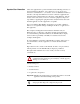
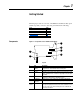
Components
Figure 1.1 Components of the 1329I DeviceNet Option
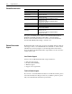
Topic Page
Components
1-1
Option Features 1-2
Required Equipment 1-2
Safety Precautions 1-3
Quick Start 1-4
#Part Description
1 Access to Unit
Switches
Rotary switches and DIP switches on the 1329I unit can be accessed
through the holes and underneath the DeviceNet option.
2 Unit Cable A ribbon cable that connects to the 1329I unit.
3 Ground A ground for the DeviceNet option. When the lock washer and a screw
from the installation kit are secured in the upper right corner, the option
is grounded.
4 Label Labels identifying the ASA serial number, manufacture date,
manufacturer, catalog number, and firmware release.
5 DIP Switches Switches that you set to configure the node address and data rate.
6DeviceNet
Connector
A DeviceNet connector that will accept an open-style linear plug.
Not
Shown
Installation Kit An installation kit consisting of one grounding wrist strap, one 10-pin
open-style linear plug for DeviceNet, screws, and a lock washer. These
items are used to secure the DeviceNet option to the 1329I unit and
connect it to the network.
3
1
2
4
5
6
Top View