
Manual


Parameters B-3
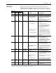
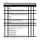
Parameter List
#
Object
Mapping
Name and Description
Access
Rule
(1)
Units/
Range
Factory
Default
Drive Display Parameters
01 0x0F-1-1 Command Frequency
Value of the presently selected speed reference.
Get 0.1 Hz None
02 0x0F-2-1 Output Frequency
Output frequency to the motor.
Get 0.1 Hz None
03 0x0F-3-1 Output Voltage
Output voltage to the motor.
Get 1 Volt None
04 0x0F-4-1 Output Current
Output current to the motor.
Get 0.1% of
Rated
Current
None
05 0x0F-5-1 Load Current
Output current to the motor due to the load.
Get 0.1% of
Rated
Current
None
06 0x0F-6-1 Bus Voltage
DC Bus voltage level.
Get 1 Volt None
07 0x0F-7-1 Power Unit Temperature
Temperature of the 1329I unit.
Get 1 °C None
08 0x0F-8-1 Analog Input
The value of the analog speed reference input (terminal 2 or 3 on the control signal terminal
block).
Get 0.1% of
Full Scale
None
09 0x0F-9-1 TB Input Status
The on (1) and off (0) state of the inputs to the control signal terminal block:
Get Bits None
10 0x0F-10-1 Last Fault
Fault number for the most recent fault.
0 = No Fault 11 = Keypad Fixed Pattern
1 = Function Loss 12 = Keypad Redundant Start
2 = Over Current 13 = TB Redundant Start
3 = Motor Overload 14 = Keypad Connect
4 = Over Voltage 15 = Under Voltage Running
5 = Under Voltage Stop 20 = DNet EEPROM Fault
6 = Over Temperature 21 = DNet Unrecoverable Fault
7 = Communication Loss 22 = No DNet Power
8 = Parameter Checksum 23 = DNet Lost I/O Connection
9 = EEPROM Drive ID 24 = DNet Forced Fault
10 = Keypad Disconnect 25 = DNet Comm Fault
Refer to Chapter
7 for troubleshooting procedures.
Get 0 to 24 None
Drive Program Parameters
30 0x0F-30-1 Minimum Frequency
Lowest frequency that the drive will output continuously. Its value must be less that Parameter
31 - [Maximum Frequency].
Get/
Set
(2)
0 Hz to
60 Hz
0 Hz
31 0x0F-31-1 Maximum Frequency
Highest frequency that the drive will output. Its value must be greater that the value of
Parameter 30 - [Minimum Frequency].
Get/
Set
(2)
50 Hz to
120 Hz
60 Hz
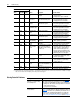
(1)
Get = Read. Set = Write. Set access is allowed only if DIP switch 10 on the 1329I Integrated drive/motor is set to On (Figure 2.3).
(2)
The parameter can be set only when the drive is stopped.
(3)
The parameter can be set only when the 1329 Integrated drive/motor does not have an active I/O connection.
Bit 7 Bit 6 Bit 5 Bit 4 Bit 3 Bit 2 Bit 1 Bit 0Bit 8Bit 9Bit 10Bit 11Bit 12Bit 13Bit 14Bit 15
Stop
Start
Reset
Forward/Reverse
Function Loss
RPM/Percent Load Displa
y
Not Used
Not UsedSpeed Preset 0
Speed Preset 1
Speed Preset 2
Not Used