
Manual

5-2 Using I/O Messaging
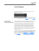
Example of I/O Messaging
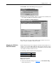
For example, Output Assembly 21 uses the following data format:
Input Assembly 71 uses the following data format:
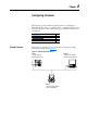
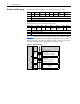
Figure 5.1
illustrates how data in Output Assembly 21 and Input Assembly
71 will be transmitted between a 1329I unit and an SLC processor. Notice
that the terms input and output are defined from the scanner’s point of view.
Also notice that explicit messaging can be transmitted as well.
Figure 5.1 Example I/O Image
Byte Bit 7 Bit 6 Bit 5 Bit 4 Bit 3 Bit 2 Bit 1 Bit 0
0NetRef Net
Control
Fault
Reset
RunRev RunFwd
1 Not Used
2 Speed Reference RPM (Low Byte)
3 Speed Reference RPM (High Byte)
Byte Bit 7 Bit 6 Bit 5 Bit 4 Bit 3 Bit 2 Bit 1 Bit 0
0At
Reference
RefFrom
Net
CtrlFrom
Net
Ready Running
Reverse
Running
Forward
Faulted
1Not Used
2 Speed Actual RPM (Low Byte)
3 Speed Actual RPM (High Byte)
SLC Scanner 1329I Unit and DeviceNet Option
DeviceNet
Output
Image
(Write)
Input
Image
(Read)
Explicit
Message
Handler
Explicit
Message
Buffer
0 - Logic Status
1 - Not Used
2 - Actual Speed (Low Byte)
3 - Actual Speed (High Byte)
0 - Logic Command
1 - Not Used
2 - Speed Reference (Low Byte)
3 - Speed Reference (High Byte)
Byte