Bulletin 1329I DeviceNet Option Catalog Number: 1329I-DN1 FRN: 1.
Important User Information Solid state equipment has operational characteristics differing from those of electromechanical equipment. “Safety Guidelines for the Application, Installation and Maintenance of Solid State Controls” (Publication SGI-1.1) describes some important differences between solid state equipment and hard-wired electromechanical devices.
Summary of Changes Summary of Changes This is the first release of this product and manual.
ii Notes: Summary of Changes
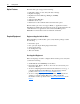
Preface Using This Manual Topic Manual Objectives Audience for This Manual Conventions Page P-1 P-1 P-1 Topic Firmware Release Number Related Documentation Rockwell Automation Support Page P-1 P-2 P-2 Manual Objectives The purpose of this manual is to provide you with information needed to apply the DeviceNet option to the 1329I Integrated Drive/Motor. It includes methods for installing, configuring, and troubleshooting this option.
P-2 Using This Manual Related Documentation For Information On: 1329I Integrated Drive Motor DeviceNet cables and components DeviceNet network installation and implementation DeviceNet Manager Software Refer To: 1329I Integrated Drive/Motor User Manual, Publication 1329I-5.0 DeviceNet Product Overview, Publication DN-2.5 DeviceNet Cable System Planning and Installation Manual, Publication 1485-6.7.2 DeviceNet Manager Software User Manual, Publication 1787-6.5.
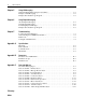
Table of Contents Preface Using This Manual Manual Objectives. . . . . . . . . . . . . . . . . . . . . . . . . . . . . . . . . . . . . . . . . . . . . . . . . . . . . . . Audience for This Manual . . . . . . . . . . . . . . . . . . . . . . . . . . . . . . . . . . . . . . . . . . . . . . . . Conventions. . . . . . . . . . . . . . . . . . . . . . . . . . . . . . . . . . . . . . . . . . . . . . . . . . . . . . . . . . . . Firmware Release Number . . . . . . . . . . . . . . . . . . . . . . . . . . . . . . . .
ii Table of Contents Chapter 5 Using I/O Messaging Understanding I/O Messaging and Assemblies . . . . . . . . . . . . . . . . . . . . . . . . . . . . . . . . . 5-1 Example of I/O Messaging . . . . . . . . . . . . . . . . . . . . . . . . . . . . . . . . . . . . . . . . . . . . . . . . 5-2 Example SLC Ladder Logic Program . . . . . . . . . . . . . . . . . . . . . . . . . . . . . . . . . . . . . . . . 5-3 Chapter 6 Using Explicit Messaging About Explicit Messaging . . . . . . . . . . . . . . . . . . . . .
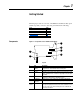
Chapter 1 Getting Started This chapter provides an overview of the Bulletin 1329I DeviceNet option and the steps that you need to start using it. It includes the following: Topic Components Option Features Required Equipment Safety Precautions Quick Start Components Page 1-1 1-2 1-2 1-3 1-4 Figure 1.
1-2 Getting Started Option Features The DeviceNet option supports the following: • • • • • • • Polled I/O, change of state, and cyclic data exchange. Explicit messaging. Explicit Unconnected Message Manager (UCMM). Autobaud. Self-generating EDS files. Faulted node recovery. Parameters for the 1329I unit and for the DeviceNet option. The DeviceNet option does not support PCCC, so applications such as DriveExplorer and DriveTools32 cannot be used to program and monitor the 1329I unit.
Getting Started Safety Precautions Please read the following safety precautions carefully ! ! ! ! ! ! ATTENTION: Hazard of injury or equipment damage exists. Only personnel familiar with the 1329I Integrated unit and DeviceNet should plan or implement the installation, start-up, configuration and subsequent maintenance of the 1329I unit. Failure to comply may result in injury and/or equipment damage. ATTENTION: Hazard of equipment damage exists.
1-4 Getting Started Quick Start This quick start is for users who have previously installed and configured a DeviceNet network and Allen-Bradley drives. It may help reduce the time of installation. Because this is a start up guide for experienced users, it does not contain detailed instructions. It does, however, reference other chapters in this manual where detailed information can be found.
Chapter 2 Installing the DeviceNet Option This chapter provides instructions for installing and wiring the DeviceNet option on the 1329I Integrated Drive/Motor.
2-2 Installing the DeviceNet Option Connecting the Option to the 1329I Unit ! ! ATTENTION: Risk of injury or death exists. A 1329I Integrated Drive/Motor and DeviceNet network may contain voltages that can cause injury or death. Remove power from the 1329I unit and network, and then verify that bus voltage has discharged to a zero before working on them. ATTENTION: Risk of equipment damage exists.
Installing the DeviceNet Option Commissioning the 1329I Unit for DeviceNet ! 2-3 ATTENTION: Risk of equipment damage exists. Pen ink or pencil lead may damage the switches on the DeviceNet option. Do not use a pen or pencil to set the switches. 1. Verify that power has been removed from the 1329I unit and network. 2. On the 1329I Integrated drive/motor, set the drive setup DIP switch in position 10. The setting takes effect when the 1329I unit first receives power.
2-4 Installing the DeviceNet Option 4. On the DeviceNet option, set switches 7 and 8 to select the data rate at which the network is operating. The default switch setting is to use the setting of Parameter 104 - [NV Baud Rate]. Data Rate 125 kBPS 250 kBPS 500 kBPS Set by Parameter 104 - [NV Baud Rate](1) (1) Switch 8 0 0 1 1 Switch 7 0 1 0 1 The default parameter setting is autobaud. 1. Verify that power has been removed from the 1329I unit and network.
Installing the DeviceNet Option 2-5 Figure 2.5 Reconnecting the Cover 1.46 Nm (13 in-lb) Display Cable 2. Tighten the screws on the cover to 1.46 Nm (13 in.-lb.). Applying Power ! ATTENTION: Risk of equipment damage, injury, or death exists. Unpredictable operation may occur if you fail to verify that connections and switch settings are compatible with your application.Verify that connections and parameter settings are compatible with your application before applying power to the 1329I unit. 1.
2-6 Notes: Installing the DeviceNet Option
Chapter 3 Configuring the 1329I Unit and DeviceNet Option This chapter provides information and instructions for configuring the 1329I Integrated drive/motor and DeviceNet Option to communicate on a DeviceNet network.
3-2 Configuring the 1329I Unit and DeviceNet Option Going Online with DeviceNet Manager You can configure a 1329I unit/DeviceNet option device offline and then download the configuration, or you can configure it online. We recommend configuring it online. 1. Start DeviceNet Manager. 2. Select Utilities > Set Up Online Connection to display the DeviceNet Driver Selection dialog box. Figure 3.1 DeviceNet Driver Selection Dialog Box 3.
Configuring the 1329I Unit and DeviceNet Option Creating an EDS File 3-3 After you go online, you can download an EDS (Electronic Data Sheet) file from any device on the network. An EDS file is a specially formatted ASCII file that provides all the information necessary for a configuration tool such as DeviceNet Manager to access and edit the parameters in a device. To create an EDS file for a 1329I unit with a DeviceNet option: 1.
3-4 Configuring the 1329I Unit and DeviceNet Option 5. Under Select Bitmap for this Device in the Create EDS Stub dialog box (Figure 3.4), click Browse. An Open dialog box appears. Figure 3.6 Open Dialog Box 6 6 6. Select the 1329I.bmp in the list box, and then click OK. The Create EDS Stub dialog box reappears. 7. Click OK. A DeviceNet Manager message box appears and asks if you want to save the EDS file to the EDS library. 8. Click OK to save the EDS file. The EDS Description dialog box appears. 9.
Configuring the 1329I Unit and DeviceNet Option 3-5 2. Double-click the icon for the 1329I unit. The Device Configuration Enhanced Mode dialog box appears. Figure 3.8 Device Configuration - Enhanced Mode Dialog Box Parameters for the 1329I unit and DeviceNet option are displayed under Parameters. You can either scroll through the parameters in the list, or you can select a specific group of parameters in the Parameter Group box.
3-6 Configuring the 1329I Unit and DeviceNet Option 3. Click OK to close the dialog box. 4. Reset the DeviceNet option. The new setting for this parameter will take effect after a reset. See Resetting the DeviceNet Option in this chapter. After setting a new node address, you must scan the network. DeviceNet Manager will then display the new address in the Network Who window (Figure 3.7) and be able to communicate with the drive so that future parameter changes take effect.
Configuring the 1329I Unit and DeviceNet Option Selecting Input and Output Assemblies 3-7 The 1329I unit uses Assembly Objects to send data to and from a scanner over an I/O connection. The terms input and output are defined from the scanner’s point of view. An output assembly is the information that is output by the scanner and consumed by the 1329I unit. An input assembly is the status data that sent by the 1329I unit and consumed as input by the scanner.
3-8 Configuring the 1329I Unit and DeviceNet Option Figure 3.12 Modifying the Network Control Parameter 2. Select Network, and then click Save to Device. 3. Click OK to close the dialog box. Enabling Network Speed Reference In order for a scanner to change the speed of the 1329I unit, the unit must be configured to accept its speed reference from the network. 1. In the Device Configuration - Enhanced Mode dialog box (Figure 3.8), double-click Parameter 36 - [Speed Ref Source].
Configuring the 1329I Unit and DeviceNet Option 3-9 Setting the Communications The communications fault action determines how the 1329I unit and DeviceNet option respond when communications are disrupted (e.g., Fault Action disconnected cable). By default, the 1329I unit is faulted and stopped. You can change this setting if your application requires a different setting. ! ATTENTION: Hazard of injury or equipment damage exists.
3-10 Configuring the 1329I Unit and DeviceNet Option Setting the Idle Action The idle action determines how the 1329I unit and DeviceNet option respond when the scanner is placed in idle/program mode. By default, the 1329I unit is sent zero data. You can change these settings if your application requires it. ! ATTENTION: Hazard of injury or equipment damage exists. Parameter 110 - [DNet Idle Mode] determines the action of the option and connected 1329I unit if the scanner is placed in idle mode.
Configuring the 1329I Unit and DeviceNet Option 3-11 Figure 3.16 Modifying the Change of State Mask 2. Select the bits (an “X” appears) that you want reviewed for changes, and then click Save to Device. 3. Click OK to close the dialog box. Resetting the DeviceNet Option For changes to some parameters in the option to take effect, you must reset the option.
3-12 Configuring the 1329I Unit and DeviceNet Option 2. Select Reset DNet, and then click Save to Device. The DeviceNet option will be reset. To view the new settings in DeviceNet Manager, you may need to scan the network. 3. Click OK to close the dialog box.
Chapter 4 Configuring a Scanner This chapter provides information and instructions for configuring an SLC 500 controller with a 1747-SDN scanner to communicate with a 1329I Integrated drive/motor using a DeviceNet option.
4-2 Configuring a Scanner Setting Up the Scan List For the scanner to communicate with a 1329I unit, the scanner must be configured and the 1329I unit’s node number must be added to its scan list. 1. Go online with DeviceNet Manager. Refer to Going Online with DeviceNet Manager in Chapter 3. 2. Select Who > Network Who. The Network Who window appears, and DeviceNet Manager scans the network for devices.
Configuring a Scanner Figure 4.4 1747-SDN Scan List Editor Dialog Box 5 5. Under Add Devices From, click Who. The Add Devices to Scan List dialog box appears. Figure 4.5 Add Devices to Scan List Dialog Box 6. Drag and drop the icon for the 1329I unit onto the scanner icon. The 1329I icon will be outlined with a square. 7. Click OK. The Scan List Editor dialog box reappears, and the 1329I node appears in the scan list.
4-4 Configuring a Scanner Figure 4.6 Scan List Editor Dialog Box 8 8 8. Click the new node to highlight it, and then click Edit I/O Parameters. The Edit Device I/O Parameters dialog box appears. Figure 4.7 Edit Device I/O Parameters Dialog Box 9. Set up the scanner for Polled I/O, Change of State, or Cyclic data exchange.
Configuring a Scanner 4-5 10.Click OK. A DeviceNet Manager message appears. Figure 4.8 DeviceNet Manager Message 11.Click Yes. The Scan List Editor dialog box reappears. It should have the size of I/O in the RX Size and Tx Size columns. Figure 4.9 1747-SDN Scan List Editor Dialog Box The scan list is now set up, and the 1329I is in the scan list. You are now ready to map the 1329I unit’s data in the scanner.
4-6 Configuring a Scanner The Datatable Map dialog box appears. Figure 4.10 Datatable Map Dialog Box 2 3 9 5 4 6 7 8 2. Next to Display Mode, select Data Entry. A dot appears in the circle. 3. Next to Data Map, select Input to map the input data. 4. In the Map Data to box, select where the data is to be placed. In our example, we will choose Discrete. 5. In the Map Data From box, select from where the data is received. In our example, it is from a Poll Message. 6. In the I:1.
Configuring a Scanner 4-7 Mapping the Output I/O 1. In the Datatable Map dialog box (Figure 4.11), select Output to map the Output data. A dot appears in the circle. Figure 4.12 Output Datatable Map 1 7 3 2 4 5 6 2. In the Map Data From box, select from where the data is transmitted. In our example, discrete is the source. 3. In the Map Data To box, select the destination of the data. In our example, the destination is a poll message. 4.
4-8 Configuring a Scanner 8. Click Close. The Scan List Editor dialog box reappears. Figure 4.14 Scan List Editor Dialog Box The data transmitted between the 1329I unit and SLC scanner is no mapped to the scanner. Saving the Configuration After creating a configuration, you should download it to the scanner. 1. In the Scan List Editor dialog box, click SDN under Save To. The Scan List Editor - Download dialog box appears. Figure 4.15 Scan List Editor - Download Dialog Box 2.
Chapter 5 Using I/O Messaging This chapter provides information about using control I/O. It includes information on the following: Topic Understanding I/O Messaging and Assemblies Example of I/O Messaging Example SLC Ladder Logic Program Page 5-1 5-2 5-3 Important: To use control I/O, you must have already configured the 1329I unit and DeviceNet option (Chapter 3) and scanner (Chapter 4).
5-2 Using I/O Messaging Example of I/O Messaging For example, Output Assembly 21 uses the following data format: Byte 0 Bit 7 Bit 6 NetRef Bit 5 Net Control Bit 4 1 2 3 Not Used Speed Reference RPM (Low Byte) Speed Reference RPM (High Byte) Bit 3 Bit 2 Fault Reset Bit 1 RunRev Bit 0 RunFwd Input Assembly 71 uses the following data format: Byte 0 1 2 3 Bit 7 Bit 6 Bit 5 Bit 4 At RefFrom CtrlFrom Ready Reference Net Net Not Used Speed Actual RPM (Low Byte) Speed Actual RPM (High Byte) Bit 3 Ru
Using I/O Messaging Example SLC Ladder Logic Program The example program in Figure 5.2 runs the 1329I unit in the forward and reverse direction. It also provides a speed reference. Note that the scanner must be in Slot 2 of the SLC 500 rack for this example. Figure 5.2 Example SLC Ladder Logic Program Enable the 1747-SDN Scanner. 1747-SDN Run Bit O:2 0000 0 1747-SDN This rung clears a fault if the 1329I unit is faulted.
5-4 Notes: Using I/O Messaging
Chapter 6 Using Explicit Messaging This chapter provides information about using explicit messaging. It includes information on the following: Topic About Explicit Messaging Using Explicit Messaging Formatting Explicit Messages Example SLC Ladder Logic Program Page 6-1 6-1 6-2 6-3 Important: In order to use explicit messaging, you must have already configured the 1329I unit and DeviceNet option (Chapter 3) and the scanner (Chapter 4).
6-2 Using Explicit Messaging Formatting Explicit Messages There are ten 32-word transaction blocks within the scanner module reserved for explicit message program control. These transaction blocks accommodate both downloading explicit message requests and uploading explicit message responses. The scanner module can accommodate one request or response for each transaction block. Each transaction block must be formatted as shown in Figure 6.1. Figure 6.
Using Explicit Messaging Example SLC Ladder Logic Program 6-3 The example ladder logic program (Figure 6.2) can be used to do explicit messaging from an SLC. This ladder program will allow the SLC 500 to use explicit messaging to read and write parameters to a 1329I Integrated drive/ motor. Running the Example Program 1. Enter data into the program. The request information will be placed in the N10 file. The first word in N10 will be the TXID and command information, which both receive a value of one.
6-4 Using Explicit Messaging Data Format for a Read and Write Parameter The data in this example is for a 1329I unit with a DeviceNet option at node address 1.
Using Explicit Messaging Example Ladder Logic Program Note that the scanner must be in Slot 2 of the SLC 500 rack for this example. Figure 6.2 Example SLC Ladder Logic Program This rung moves the Explicit Message Request data from the SLC500 processor to the 1747-SDN. Explicit Msg Request enable bit N7:0 0000 0 Generate Explicit Request Only Once. B3:0 OSR 0 Copy Request data from the SLC to the SDN Scanner COP Copy File Source #N10:0 Dest #M0:2.
6-6 Notes: Using Explicit Messaging
Chapter 7 Troubleshooting This chapter contains information for diagnosing and correcting potential problems. Topic Locating the Status Indicators Understanding the COMM Status Indicator Fault Codes Solving Potential Problems Locating the Status Indicators Page 7-1 7-2 7-3 7-4 The 1329I Integrated drive/motor has a COMM status indicator that you can use to determine the status of the 1329I unit and DeviceNet communications. Figure 7.
7-2 Troubleshooting Understanding the COMM Status Indicator The COMM status indicator provides status information on the DeviceNet option. Important: When power is first applied to the DeviceNet option, the COMM status indicator flashes green for 1/4 second, red for 1/4 second, and then goes blank while the communication module finishes its initialization. Color State None What It Means: What To Do: The option is not receiving power from • Check DeviceNet power and cable the network.
Troubleshooting Fault Codes When there is a fault, you can view the fault code using the value in Parameter 10 - [Last Fault], the value of Class 0x29 (Control Supervisor Object), Instance 1, Attribute 13 (Fault Code), or the display on the keypad,. Fault Codes (1) Parameter Value DeviceNet Display 0 0x0000 1 0x5300 F.FL Name No Fault Function Loss Description Normal operation. Open connection on Function Loss control terminal block inputs (terminals 7 and 11). 2 Over Current Shaft rotation blocked.
7-4 Troubleshooting Fault Codes (1) Parameter Value DeviceNet Display 9 0x6312 F.Id Name EEPROM Drive ID Description Contents of the EEPROM is corrupted. 10 0x7700 F.dcn Keypad Disconnect Keypad cable disconnected while 1329I unit under power. 11 0x7701 F.ddP Keypad Fixed Pattern Keypad cable connected while 1329I unit under power. 12 0x7702 F.dSF Keypad Keypad hardware failure. Redundant Start 13 0x5301 F.rSF TB Redundant Start 14 0x7703 F.
Appendix Specifications Appendix A provides the specifications for the DeviceNet option. Electrical Network Supply Voltage Node Current Consumption Power Consumption 11 to 25 VDC 40 mA(1) 0.5 Watt maximum (1) Use this value to size the network current draw from the power supply.
A-2 Notes: Specifications
Appendix B Parameters Appendix B contains a list of the parameters in the 1329I Integrated drive/ motor and the DeviceNet option.
B-2 Parameters Parameter Groups Parameters in the 1329I Integrated drive/motor are grouped into either the Display group or the Program group. Parameters in the Display group are read only. You can get their values, but you cannot change their values. Parameters in the Program group are read/write. You can get and set their values. When a DeviceNet option is connected, its parameters are grouped in the DNet Config group. Its parameters are also read/write. Figure B.
Parameters B-3 Parameter List Object # Name and Description Mapping Drive Display Parameters 01 0x0F-1-1 Command Frequency Value of the presently selected speed reference. 02 0x0F-2-1 Output Frequency Output frequency to the motor. 03 0x0F-3-1 Output Voltage Output voltage to the motor. 04 0x0F-4-1 Output Current Output current to the motor. Access Rule (1) Units/ Range Factory Default Get 0.1 Hz None Get 0.
B-4 Parameters # 32 Object Mapping 0x0F-32-1 33 0x0F-33-1 34 0x0F-34-1 35 0x0F-35-1 Name and Description Accel Time Time for the drive to ramp from 0 Hz to the value of Parameter 31 - [Maximum Frequency]. The accel time is linear. Decel Time Time for the drive to ramp from the value of Parameter 31 - [Maximum Frequency] to 0 Hz. The decel ramp is linear. Start Source Source of the start command.
Parameters # 44 Object Mapping 0x0F-44-1 Name and Description Stop Select Stopping mode used by the drive when a stop is initiated. 0 = Coast to stop 1 = Ramp to stop 45 0x0F-45-1 Reverse Disable Disables reverse rotation of the motor. 0 = Reverse enabled 1 = Reverse disabled 46 0x0F-46-1 IR Compensation Compensation for the voltage drop across the stator resistance in an induction motor. A voltage is added to the commanded output voltage based on the load current.
B-6 Parameters Object # Name and Description Mapping 102 0x0F-102-1 Switches Baud The state of the baud rate DIP switches (7 – 8). 0 = 125K BPS 1 = 250K BPS 2 = 500K BPS 3 = Use nonvolatile parameters for node address and baud rate settings. 103 0x0F-103-1 NV MAC ID Node address independent of the node address DIP switches. To use this address, set both baud rate switches to On before power up. Changes to this parameter take effect only after power is cycled.
Parameters Object # Name and Description Mapping 108 0x0F-108-1 Input Assembly The input assembly instance that is used for polled messaging with the master. The input assembly defines the data format that the drive sends to the master in response to a polled message from the master. This parameter determines the format of data being sent to the master. It is named input assembly because the DeviceNet specification refers to all assemblies as they relate to the master.
B-8 Parameters Object # Name and Description Mapping 111 0x0F-111-1 DNet SW Version Software version of the DeviceNet option. The number is in the form of xx.yyy where xx indicates the major revision level and yyy indicates the minor revision level. 112 0x0F-112-1 COS Mask A 16-bit mask used to enable automatic change of state messages. A 0 disables the indicated status from causing an automatic message. A 1 enables the status. The mask is applied to the defined input status assembly.
Appendix C DeviceNet Objects This Appendix provides information on the DeviceNet objects supported by the 161 AC drive for DeviceNet.
C-2 DeviceNet Objects Class Code 0x01 – Identity Object Class Attributes Attribute ID 1 2 3 6 7 Access Rule Get Get Get Get Get Name Revision Max Instance Number of Instances Max ID Class Max ID Instance Data Type UINT UINT UINT UINT UINT Value 1 2 2 7 7 Number of Instances: 2 Instance 1 Attributes: Drive Instance Attribute ID 1 2 3 4 Access Rule Get Get Get Get 5 Get 6 7 Get Get 9 Get Name Vendor ID Device Type Product Code Revision Major Revision Minor Revision Status Data Type UINT UINT
DeviceNet Objects Class Code 0x02 – Message Class Attributes Router Object Attribute ID Access Rule 1 6 7 Get Get Get C-3 Name Revision Max ID Class Max ID Instance Data Type UINT UINT UINT Value 1 7 4 Value 8 Number of connections currently used by system components A list of the connection IDs of the currently active connections Instance Attributes Attribute ID 2 3 Access Rule Get Get Name Number Available Number Active Data Type UINT UINT 4 Get Active Connections Array of: UINT Common Ser
C-4 DeviceNet Objects Class Code 0x03 – DeviceNet Object Class Attributes Attribute ID 1 Access Rule Get Name Revision Data Type UINT Value 2 Data Type USINT USINT BOOL Value 0 to 63 0 to 2 0 = Hold in error state 1 = Reset CAN chip 0 to 255 Instance 1 Attributes Attribute ID 1 2 3 Access Rule Get/Set Get/Set Get/Set Name MAC ID Baud Rate Bus Off Interrupt 4 5 Get/Set Get Bus-off Counter Allocation Information Allocation Choice Master Node Address 6 Get 7 Get 8 9 Get Get (1) Allocatio
DeviceNet Objects Class Code 0x04 – Assembly Object C-5 Class Attributes Attribute ID 1 2 Access Rule Get Get Name Revision Max Instance Data Type UINT UINT Value 2 106 Instance 1 to 106 Attributes: I/O Instances Attribute ID Access Rule 3 Get Name Data Data Type Min/Max Default Description See instance data format for individual I/O assemblies on page C-6 to C-8.
C-6 DeviceNet Objects Class Code 0x04 – Assembly Object (Continued) Instance Data Format: Output Assemblies Instance 1 Data Format (Basic Contactor Output Assembly) Byte Bit 7 Bit 6 Bit 5 Bit 4 Bit 3 Bit 2 0 Instance 2 Data Format (Basic Overload Output Assembly) Byte Bit 7 Bit 6 Bit 5 Bit 4 Bit 3 0 Bit 1 Bit 0 Run Bit 2 Bit 1 Fault Reset Bit 0 Instance 3 Data Format (Basic Motor Starter Output Assembly) Byte Bit 7 Bit 6 Bit 5 Bit 4 Bit 3 Bit 2 Bit 1 0 Fault Reset Bit 0 Run Instance 4 Data Format
DeviceNet Objects Class Code 0x04 – Assembly Object (Continued) C-7 Instance Data Format: Output Assemblies (Continued) Instance 106 Data Format (Preset Control with Speed) Byte Bit 7 Bit 6 Bit 5 Bit 4 Bit 3 0 1 2(1) Speed Ref Hz (0.1 Hz) (Low Byte)(2) (1) 3 Speed Ref Hz (0.1 Hz) (High Byte)(2) Bit 2 Bit 1 Fault Reset RunRev Preset 2 Preset 1 Bit 0 RunFwd Preset 0 (1) If speed references are outside of their min/max limits, the drive ignores them and previous speed reference will be maintained.
C-8 DeviceNet Objects Class Code 0x04 – Assembly Object (Continued) Instance Data Format: Input Assemblies Instance 50 Data Format (Basic Overload/Contactor Input Assembly) Byte Bit 7 Bit 6 Bit 5 Bit 4 Bit 3 Bit 2 0 Bit 1 Instance 51 Data Format (Extended Overload/Contactor Input Assembly) Byte Bit 7 Bit 6 Bit 5 Bit 4 Bit 3 Bit 2 0 CtrlFrom Net Instance 52 Basic Motor Control Byte Bit 7 Bit 6 Bit 5 0 Bit 4 Bit 3 Bit 1 Bit 0 Faulted Bit 0 Faulted Bit 2 Bit 1 Running1 Bit 0 Faulted/Trip Instance
DeviceNet Objects Class Code 0x05 – Connection Object C-9 Class Attribute Attribute ID 1 Access Rule Get Name Revision Data Type UINT Value 1 Instance 1 Attributes: Master/Slave Explicit Message Connection Attribute Access ID Rule 1 Get Name State Data Type USINT 2 3 4 Get Get Get InstanceType Transport Class Trigger Produced Connection ID USINT USINT UINT 5 Get Consumed Connection ID UINT 6 7 8 9 12 Get Get Get Get/Set Get/Set Initial Comm.
C-10 DeviceNet Objects Class Code 0x05 – Connection Object (Continued) Instance 2 Attributes: Polled I/O Connection (Continued) Attribute Access ID Rule 14 Get Name Produced Connection Path 15 16 Consumed Connection Path Length UINT Consumed Connection Path (1) Get Get Data Type Value 0x20, 0x04, 0x24, XX, 0x30, 0x03(1) 6 0x20, 0x04, 0x24, XX, 0x30, 0x03(1) Refer to the DeviceNet specification for a description of the connection path.
DeviceNet Objects Class Code 0x05 – Connection Object (Continued) C-11 Instances 6 through 10: Explicit Message Connections Attribute Access ID Rule 1 Get Name State Data Type USINT 2 3 4 Get Get Get InstanceType Transport Class Trigger Produced Connection ID USINT USINT UINT 5 Get Consumed Connection ID UINT 6 7 8 9 12 Get Get Get Get/Set Get/Set Initial Comm.
C-12 DeviceNet Objects Class Code 0x0F – Parameter Object Class Attributes Attribute ID 1 2 8 9 10 Access Rule Get Get Get Get Get Name Revision Max Instance Parameter Class Descriptor Configuration Assembly Instance Native Language Data Type UINT UINT WORD UINT USINT Value 1 113 0x0B 0 0 = English Instance 1 through 113 Attributes Attribute ID 1 2 3 Access Rule Get/Set Get Get Name Parameter Value Link Path Size Link Path 4 Get Descriptor WORD 5 Get Data Type USINT 6 7 8 9 10 11 12 13 14
DeviceNet Objects Class Code 0x0F – Parameter Object (Continued) Common Services Service Code 0x01 0x05 0x0E 0x10 0x4B Implemented for Class Instance Yes Yes Yes No Yes Yes No Yes No Yes Service Name Get_Attributes_All Reset Get_Attribute_Single Set_Attribute_Single Get_Enum_String C-13
C-14 DeviceNet Objects Class Code 0x10 – Parameter Group Object Class Attributes Attribute ID 1 2 8 Access Rule Get Get Get Name Revision Max Instance Native Language Data Type UINT UINT USINT Value 1 3 0 = English Instance 1 Attributes: Drive Display Instance Attribute ID 1 2 3 4 5 6 7 8 9 10 11 12 Access Rule Get Get Get Get Get Get Get Get Get Get Get Get Name Group Name String Number of Members in Group 1st Parameter Number in Group 2nd Parameter Number in Group 3rd Parameter Number in Group 4
DeviceNet Objects Class Code 0x10 – Parameter Group Object (Continued) C-15 Instance 2 Attributes: Drive Program Instance (Continued) Attribute ID 26 27 28 29 30 Access Rule Get Get Get Get Get Name 24th Parameter Number in Group 25th Parameter Number in Group 26th Parameter Number in Group 27th Parameter Number in Group 28th Parameter Number in Group Data Type UINT UINT UINT UINT UINT Value 53 54 55 56 57 Data Type SHORT_STRING UINT UINT UINT UINT UINT UINT UINT UINT UINT UINT UINT UINT UINT UINT
C-16 DeviceNet Objects Class Code 0x28 – Motor Data Object Class Attributes Attribute ID 1 2 6 7 Access Rule Get Get Get Get Name Revision Max Instance Max ID Class Max ID Instance Data Type UINT UINT UINT UINT Value 1 1 7 15 Instance 1 Attributes Attribute ID 1 2 3 4 5 6 7 8 Access Rule Get Get Get Get Get Get Get Get 9 Get 11 Get/Set(2) 12 15 Get Get/Set Name Number of Attributes Attributes List Motor Type Catalog Number Manufacturer Rated Current Rated Voltage Rated Power at Rated Frequen
DeviceNet Objects Class Code 0x29 – Control Supervisor Object C-17 Class Attributes Attribute ID 1 2 6 7 Access Rule Get Get Get Get Name Revision Max Instance Max ID Class Max ID Instance Data Type UINT UINT UINT UINT Value 1 1 7 17 Instance 1 Attributes Attribute ID Access Rule Name Data Type 1 Get Number of USINT Attributes 2 Get Attributes List Array of USINT 3 Get/Set(1) Run 1 BOOL 4 Get/Set(1) Run 2 BOOL 5 Get/Set(1) NetCtrl BOOL 6 Get State USINT 7 Get Running 1 BOOL 8 Get Running 2
C-18 DeviceNet Objects Class Code 0x29 – Control Supervisor Object (Continued) Instance 1 Attributes (Continued) Attribute ID Access Rule Name Data Type 14 Get Warn Code UINT 15 Get Ctrl From Net BOOL 16 Get/Set 17 Get/Set 102(1) Get/Set 103(1) Get/Set 104(1) Get/Set (1) DNet Fault Mode Force Fault/ Trip DNet Preset Command DNet Speed Ref RPM DNet Speed Ref Hz BOOL Value 0 0 = TB or keypad control 1 = Network control 0 = Fault and Stop 1 = Ignore 0 -> 1 = Force fault USINT 0 to 7 UINT 0
DeviceNet Objects Class Code 0x29 – Control Supervisor Object (Continued) C-19 Run/Stop Event Matrix Attribute 5, NetCtrl is used to request that Run/Stop events be controlled from the network. The following must occur before Run/Stop control is accomplished from the network: • Attribute 15, CtrlFromNet is set to 1 by the device in response to a NetCtrl request.
C-20 DeviceNet Objects Class Code 0x2A – AC Drive Class Attributes Object Attribute ID Access Rule 1 2 6 7 Get Get Get Get Name Revision Max Instance Max ID Class Max ID Instance Data Type UINT UINT UINT UINT Value 1 1 7 29 Instance 1 Attributes Attribute ID 1 2 Access Rule Get Get Name Number of Attributes Attributes List 3 Get At Reference Data Type USINT Array of USINT BOOL 4 Get/Set Net Ref BOOL 6 7 8 9 10 16 17 18 19 20 21 22 23 27 28 29 Get Get Get Get Get Get Get Get/Set Get/Set Ge
DeviceNet Objects Class Code 0x2B – Acknowledge Handler Object C-21 Class Attributes Attribute ID 1 2 Access Rule Get Get Name Revision Max Instance Data Type UINT UINT Value 1 1 Value Timer resolution of 8 msec.
C-22 Notes: DeviceNet Objects
Glossary Numeric 1329I Integrated/Drive Motor The 1329I Integrated Drive Motor is an AC drive integrally mounted with an inverter duty motor. It consists of a drive section and a motor section. It may be connected to a DeviceNet network with an DeviceNet option. In this manual, the 1329I Integrated Drive Motor is also referred to as “1329I unit,” “drive,” or “unit.
Glossary-2 D Data Rate The data rate, sometimes called baud rate, is the speed at which data is transferred on the DeviceNet network. The available data rates depend on the type of cable and total cable length used on the network: Cable ThickTrunk Line Thin Trunk Line Maximum Drop Length Cumulative Drop Length Maximum Cable Length Based on Data Rate 125 K 250 K 500 K 500 m (1,640 ft.) 250 m (820 ft.) 100 m (328 ft.) 100 m (328 ft.) 100 m (328 ft.) 100 m (328 ft.) 6 m (20 ft.) 6 m (20 ft.) 6 m (20 ft.
Glossary-3 DeviceNet Manager Software DeviceNet Manager software is a tool for configuring and monitoring DeviceNet networks and connected devices. It is a 16-bit Windows application that runs on Windows 95, Windows 98, and Windows NT ® (4.0 or greater). Information about DeviceNet Manager software can be accessed at http://www.ab.com.
Glossary-4 I I/O Messaging I/O messages are used to transmit time-critical I/O data that controls the drive. I/O messages are sometimes referred to as implicit messages. The I/O messages used for the 1329I unit depend on the input and output assemblies that you are using. Idle Action An idle action determines how the option and connected 1329I unit act when the processor is placed into an idle mode. L Logic Command/Status The logic command/status is used to control and monitor the 1329I unit (e.g.
Glossary-5 Producer/Consumer Network DeviceNet is a producer/consumer network. On producer/consumer networks, packets are identified by content rather than by an explicit destination. If a node needs the packet, it will accept the identifier and consume the packet. The source therefore sends a packet once and all the nodes consume the same packet if they need it. Data is therefore produced once, regardless of the number of consumers.
Glossary-6 Notes:
Index Numerics 10-pin linear plug 2-4 1329I Integrated drive/motor definition G-1 mapping its data in the scanner 4-5 parameters B-1–B-8 classes G-1 COMM status indicator at first power up 2-5 locating 7-1 understanding 7-2 Command Frequency parameter B-3 communications fault action 3-9 A communications module, refer to DeviceNet option AC Drive object C-20 communications specifications A-1 Accel Time parameter B-4 components 1-1 accessing parameters 3-4 configuration tools 3-1 Acknowledge Handler
Index-2 DeviceNet cables 2-4 definition G-2 example network G-2 objects C-1–C-21 DeviceNet Configuration dialog box 3-5 DeviceNet Manager accessing parameters with 3-4 creating EDS files 3-3 definition G-3 going online 3-2 mapping data in a scanner 4-5 saving a configuration 4-8 setting up the scan list 4-2 web site G-3 DeviceNet object C-4 DeviceNet option adding to a scan list 4-2 components 1-1 configuring 3-1–3-12 definition G-3 features 1-2 firmware release number P-1 installation 2-1–2-5 mapping its
Index-3 input assemblies bit definitions C-8 definition G-1 parameter B-7 selecting 3-7 Input Assembly parameter B-7 input I/O illustrated example 5-2 mapping in the scanner 4-5 Input Status parameter B-3 installation applying power 2-5 commissioning the unit for DeviceNet 2-3 connecting the cover 2-4 connecting the option to the unit 2-2 connecting to the network 2-4 DeviceNet option 2-1–2-5 EMC Directive 89/336/EEC 2-1 Low Voltage Directive 73/23/EEC 2-1 preparing 2-1 IR compensation parameter B-5 mecha
Index-4 parameters accessing 3-4 groups B-2 numeric list B-3 setting DIP switch 10 to enable 2-3 specific name, refer to name PCCC 1-2 polled I/O definition G-4 setting up scan list 4-2 power 2-5 Power Unit Temperature parameter B-3 Preset Speed 1 - 7 parameters B-5 processors, refer to controllers producer/consumer networks G-5 product codes B-1 programmable logic controllers, refer to controllers protocol A-1 scanner configuring 4-1–4-8 definition G-5 explicit messaging 6-1 ladder logic program 5-3, 6-3
Index-5 W warnings 1-3 web site P-2 wiring 2-4 Z zero data definition G-5 selecting 3-10
Index-6 Notes:
We Want Our Manuals to be the Best! You can help! Our manuals must meet the needs of you, the user. This is your opportunity to make sure they do just that. By filling out this form you can help us provide the most useful, thorough, and accurate manuals available. Please take a few minutes to tell us what you think - then mail this form or FAX it.
FOLD HERE FOLD HERE NO POSTAGE NECESSARY IF MAILED IN THE UNITED STATES BUSINESS REPLY MAIL FIRST CLASS PERMIT NO. 413 MEQUON, WI POSTAGE WILL BE PAID BY ADDRESSEE ALLEN-BRADLEY Attn: Marketing Communications P.O.
DeviceNet is a trademark of the Open DeviceNet Vendor Association. RSLogix and RSNetWorx are trademarks of Rockwell Software. Windows, Windows NT and Microsoft are trademarks of Microsoft Corporation.
Publication 1329I-5.3 – January, 2000 P/N 194416 (01) Copyright 2000 Rockwell International Corporation. All rights reserved. Printed in USA.