
Manual

Publication 1326-IN025B-EN-P - May 2007
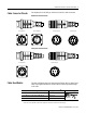
2 Bulkhead Connections for Series B 1326 Cables
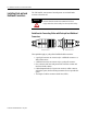
Feedback Cable Wiring
Connector wiring pinouts and diagrams are provided for the
1326-CCUx-Dx and 1326-CCUT-Ex feedback cables. Refer to
page 4 for
power cable information, and page 8 for installation instructions.
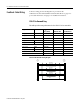
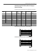
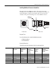
1326-CCUx-Dx-xxx Wiring
This table provides wiring information for the 1326-CCUx-Dx-xxx cables.
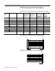
1326-CCU-DE-xxx Cable Wiring Diagram
Signal Wire Color Gauge
mm
2
(AWG)
1326-CCU-DE
Connector Pin
1326-CCUT-DL
Connector Pin
Axis_0_R1 Black 0.518 (20) A A
Axis_0_R2 White 0.518 (20) B B
Shield 0.518 (20) — C
Axis_0_S1 Black 0.518 (20) D D
Axis_0_S3 Red 0.518 (20) E E
Shield 0.518 (20) — F
Axis_0_S4 Black 0.518 (20) H H
Axis_0_S2 Green 0.518 (20) G G
Shield 0.518 (20) — I
Overall shield N/A Female Shell J and Shell
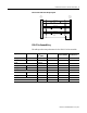
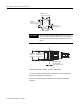
Pair #1: Black
Pair #1: White
Shield
Pair #2: Black
Pair #2: Red
Shield
Pair #3: Black
Pair #3: Green
Shield
Shield
A
B
D
E
H
G
A
B
D
E
H
G
Male
Connector
Pin
Female
Connector
Contact
Bulkhead