
User Manual Owner's manual

DC Motors 11
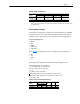
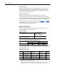
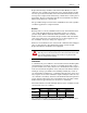
Table E Radial Load Capacity
1
1
Data for motors with roller bearings at the drive end (back end). Motors with ball bearings at the drive end are
for coupled duty only.
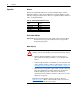
Deriving Motor Constants
Various motor constants are required to set control functions for stabilized
operation of motor and controls. The following information will make it
possible to derive approximate motor constants from the nameplate data.
Required Nameplate Data
• Frame
• HP
• RPM
• Volts (Va)
• Amps (Ia)
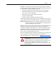
From
Table F, the following factors are available, based on frame size.
• Ra´
• La´
• WK
2
•τe´
This will provide approximate results with a ±25% margin of error.
The following data can be derived:
La = La´ x (Va/rpm)
2
Arm. Circ. Ind. (millihenries)
Ra = Ra´ x (Va/rpm)
2
Arm. Circ. Resistance
τe = τe´
τe´ = La/Ra x 10
3
Elec.Time Constant
J (SEC) = WK
2
x (rpm)
2
/1.62 x (10)
6
x hp where WK
2
is in terms of lb-ft
2
J (SEC) = WK
2
x (rpm)
2
/0.0922 x (10)
6
x kw where WK
2
is in terms of kg-m
2
R = Ia x Ra/(Va – IaRa)
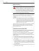
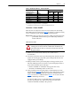
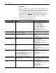
Table F Resistance & Inductance Factors
Frame
Capacity at End of Shaft in kg (lbs.)
2500 RPM 1750 RPM 1150 RPM 850 RPM
DC210ATZ &
DC180ATZ
140.6 (310) 156.5 (345) 179.2 (395) 200.0 (440)
C180ATZ 226.8 (500) 256.3 (565) 283.5 (625) 283.5 (625)
Frame
WK
2
Ra La τelb.-ft.
2
kg.-m.
2
C1811ATZ 0.683 0.029 56.6 616 0.011
C1812ATZ 0.787 0.033 40.5 500 0.012