Installation, Operation and Maintenance Manual DC Motors • Frames DC180ATZ, C180ATZ and DC210ATZ
DC Motors General Description The products described in this publication are designed specifically for use on rectified power. The basic design includes Class F Insulation, 1.0 Service Factor, 40 degree C (104 degree F) ambient, continuous duty, with drip-proof guarded and force-ventilated enclosure, with horsepower speed ratings, overload and voltage in accordance with NEMA Standards. A wide variety of modifications, enclosures and accessories is available.
DC Motors 3 Handling ! ATTENTION: Eyebolt(s) or lifting lug(s) are intended for lifting the motor only with the standard accessories such as tachometer, brakes, etc., mounted by Allen-Bradley. The lifting means on the motor must not be used to lift the unit plus additional equipment. The lifting means on the motor cannot be used to lift assemblies or equipment mounted on a common base. Failure to observe this precaution could result in personal injury.
DC Motors Location Locate the machine where the ambient temperature is not over 40 degrees C (104 degrees F) and where clean air has free access to ventilating intake and outlet openings. Except for machines with a suitable protective enclosure, the location should be clean and dry. Important: Sufficient clearance must be provided on all inlet and outlet openings to provide for unrestricted flow of air. Separately ventilated motors with exhaust to ambient (pipe-in only) must have at least 152.
DC Motors 5 For example, a motor designed for a D type of power supply may be used on a C power supply having the same voltage rating. The types of power supplies are defined as follows.
DC Motors Thermostat (Thermal Protector) Important: When motors are provided with thermal protection (typically thermostats), it is important to properly connect and apply the devices. This will ensure that the motor is properly protected from being operated if thermal limits are reached and/or exceeded. The control system must be configured to reduce the motor load and/or shut down the motor control system to allow the motor to cool to a level within acceptable operating ranges.
DC Motors 7 Mounting Motors must be mounted on a rigid, solid base or foundation. Poor base construction may cause resonances in the motor/base assembly which can result in bearing failure and other motor damage. All hold down bolts must be the correct grade for the type of mounting and must be torqued to their recommended value. Table A Recommended Torque Hole Diameter Bolt Size and SAE Grade I Dry Components-Not Lubricated Frame mm (in.) Thread N-m (lb.-ft.) C180ATZ 11.2 (0.44) 3/8-16 1.
DC Motors Direction of Rotation Unless otherwise ordered, brush rigging is assembled for NEMA standard direction of rotation, counterclockwise for motors and clockwise for generators facing the commutator end. These motors will operate in either direction of rotation, without changing the angle of the brush holders for normal field weakened speed ranges. Extended field weakened speed range motors should have the direction of rotation specified.
DC Motors 9 The speeds given in Table B are the maximum mechanically safe operating speeds for frames with standard construction. These speeds must not be exceeded under any condition. Motor control must hold the maximum speed under any load condition including no-load within the maximum safe speed.
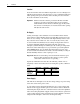
DC Motors Shaft Extension and Method Of Drive V-belts should be within the limits of NEMA Standard MG1-14.67.a. Frames DC180ATZ, C180ATZ, DC210ATZ are supplied with the same size shaft for either coupled or belted drives. Table C Multipliers for Drives other than V-belt Drive Flat Belt (See Note 1) Timing Belt (See Note 2) Chain Sprocket Spur Gear Helical Gear Multiplier 1.33 0.9 0.7 0.75 0.85 1 The above multiplier is intended for use with conventional single-ply flat, belts.
DC Motors 11 Table E Radial Load Capacity 1 Capacity at End of Shaft in kg (lbs.) Frame 2500 RPM 1750 RPM 1150 RPM DC210ATZ & 140.6 (310) 156.5 (345) 179.2 (395) DC180ATZ C180ATZ 226.8 (500) 256.3 (565) 283.5 (625) 1 850 RPM 200.0 (440) 283.5 (625) Data for motors with roller bearings at the drive end (back end). Motors with ball bearings at the drive end are for coupled duty only.
DC Motors Operation Balance Motors are dynamically balanced to commercial limits unless ordered differently. Balance is done with a full length 1/2 height shaft key. A full shaft key is shipped with the motor. Sheave or coupling should be balanced with a 1/2 height shaft key. Table G Standard Dynamic Balance Limits Highest Rated Speed (RPM) 3,000 - 4,000 1,500 - 2,999 1,000 - 1,499 Up to 999 Maximum Amplitude (Inches) 0.0010 0.0015 0.0020 0.
DC Motors 13 In addition to observing the above precaution, all precautions (Attentions) mentioned in this document should be observed. The following items must be checked before starting and during operation. • The armature should rotate freely and be clear of any obstructions. • The brushes should move easily in their holders and should make proper contact on the commutator. • The interior of the motor should be clean and dry. • Connections must be tight.
DC Motors DC Motor Field Heating ! ATTENTION: To guard against motor damage caused by inadequate ventilation, assure that motors designed for forced ventilation as standard have cooling air when fields are excited at rated voltage. Installations having the air supply interrupted when the motor is not operating must have field disconnected or field voltage reduced to 67%, rated by means of field economizing resistor and relay.
DC Motors 15 4. When contact is made, the needle will first deflect in either the up scale or down scale direction and then return to zero. Deflection will be in the opposite direction when contact is broken. 5. Relative polarities of the shunt and series fields are correct (ampere-turns are cumulative) if the voltmeter needle deflects up scale when contact is made and down scale when contact is broken. 6.
DC Motors Drive End Bearing Bearing fits in machined cavity in bracket with inner cap. To regrease bearing, remove bracket (four nuts hold bracket to frame) and inner cap (two bolts). Clean old grease from bearing and cavity and repack with Chevron SRI-2 or equivalent grease. Commutator End Bearing Bearing has single shield and single seal with seal on side facing commutator. To regrease bearing, snap out brushes and remove bracket (four nuts hold bracket to frame).
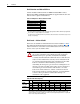
DC Motors 17 Table J Relubrication Periods – Frames C180ATZ Maximum Normal Operating Speed (RPM) 1 3450 and higher 2400 - 3449 1700 - 2399 800 - 1699 500 - 799 499 and lower 1 2 Frame C180ATZ C180ATZ C180ATZ C180ATZ C180ATZ C180ATZ Relubrication Interval (Months) 2 Standard Severe Extreme Service Service Service 9 4 1 24 9 3 36 12 3 36 24 8 48 36 12 48 36 12 Maximum speed occupying more than 30% of operating time. For Tandem drives increase frequency of lubrication by multiplying values by 0.8.
DC Motors In general, mixing of greases is not recommended. If an incompatible grease is used, the lube system must be repacked completely with the new grease. 5. Wipe away any excess grease at the grease drain or relief and replace drain plugs. Repacking Bearings or Greasing New Bearings When existing bearings have been completely cleaned of old grease or when bearings are replaced, use this procedure for packing the bearing. 1.
DC Motors 19 Replacement bearings should be ordered from Allen-Bradley in order to obtain the same carefully selected bearing as the original. Bearings should never be exposed by disassembly of the motor unless absolutely necessary for inspection or replacement of the bearing or maintenance in other parts of the machine. Protect good bearings from dirt and contamination at all times. Most bearing failures are caused by dirt.
DC Motors Commutation Intermittent sparking due to overloads or slight visible sparking does not necessarily indicate poor commutation. Poor commutation exists when there is excessive sparking requiring abnormal maintenance. Every case of excessive sparking should be investigated to determine the cause and correct it. The chart in Table K may help in analyzing commutation problems. DC motors and generators are brushed for full load current.
DC Motors 21 Windings For long life, keep windings clean and dry. Dirt or dust can be removed by wiping them with a clean cloth, by blowing with clean, dry, low pressure air or by vacuum cleaner. Oil or grease can be removed with a cloth moistened with mineral solvent. Be sure not to get any solvent on the commutator and observe all product warnings. Filters – Cleaning When supplied, filters on motors must be kept clean to assure proper air flow and cooling of the motor.
DC Motors Air Gap And Shimming (Frame C180ATZ) Main Pole Steel or brass shims, when used, are placed between pole and frame. If for any reason the shims are removed they must be replaced under the same poles. Main pole bolts are steel SAE Grade 5 (120,000 psi). Axial Float Frames C180ATZ have wavy spring washers between B.E. bracket and bearing. Axial float should be within the limits listed on the chart below. Axial Float Frame All Maximum 1.22 mm (0.048 in.) Minimum 0.20 mm (0.08 in.
DC Motors 23 Brush Rigging and Brush Holders The brush holders in all motors are often constant pressure design and do not require nor are capable of adjustment over the life of the brushes. DC180ATZ & DC210ATZ Conduit box is attached to the commutator end top hand hole cover and cannot be located on the side. C180ATZ Conduit box is located on the commutator end bracket.
Online Documentation The latest motor information can be obtained from the Allen-Bradley Drives & Motors home page on the World Wide Web at: http://www.controlmatched.com Publication 1325L-UM001B-EN-P – August, 2001 Supersedes 1325L-UM001A-EN-P dated May, 2001 Copyright © 2001 Rockwell Automation. All rights reserved. Printed in USA.