Installation, Operation and Maintenance Manual DC Motors • Frames C210ATZ - C440ATZ • Specifically designed for operation from rectified power
DC Motors General Description The products described in this publication are designed specifically for use on rectified power. The basic design includes Class F Insulation, 1.0 Service Factor, 40 degree C (104 degree F) ambient, continuous duty, with enclosure, horsepower and speed ratings, overload and voltage in accordance with NEMA Standards. A wide variety of modifications, enclosures and accessories is available.
DC Motors Receiving and Handling 3 Acceptance Thoroughly inspect this equipment before accepting shipment from the transportation company. If any of the goods called for in the bill of lading or express receipt are damaged or the quantity is short, do not accept them until the freight or express agent makes an appropriate notation on your freight bill or express receipt.
Installation DC Motors DC motors have characteristics which can cause serious or fatal injury unless they are selected, installed, maintained and operated by qualified personnel familiar with special requirements of DC machines.
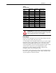
DC Motors 5 Table A Air Volume Chart Base Speed RPM ALL ALL ALL ALL ALL ALL ALL ALL ALL ALL ALL ALL ALL ALL ALL Frame C2113ATZ C2115ATZ C2512ATZ C2514ATZ C2515ATZ C2812ATZ C2813ATZ C2815ATZ C3210ATZ C3212ATZ C3214ATZ C3612ATZ C3613ATZ C400ATZ C440ATZ ! Air Volume CFM 300 290 425 385 385 550 530 530 800 800 700 1000 950 1200 1650 Static Pressure Inches of Water 2.25 4.1 2.0 3.4 3.4 3.25 3.75 3.75 3.5 3.5 4.0 4.0 5.1 4.0 7.
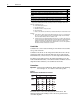
DC Motors Description DC generator, battery or twelve pulse/cycle, 6 phase, full control Six pulse cycle, 3 phase, full control 230 or 460 volt, 60 Hz input to rectifier Three pulse/cycle, 3 phase, semi-bridge, half control 230 or 460 volt, 60 Hz input to rectifier Three pulse/cycle, 3 phase, half-wave (single way) 460 volt, 60 Hz input to rectifier Two pulse/cycle, 1 phase full wave (bridge circuit with 2 controlled rectifiers and 2uncontrolled rectifiers with free wheeling rectifier) 230 volt, 60 Hz i
DC Motors Important: 7 If motor is supplied with dual voltage shunt fields, connections must be made for appropriate voltage.
DC Motors Important: Motors with an overspeed switch must have the overspeed switch terminals properly connected in the control circuit to remove armature power when the switch reaches the set speed. Grounding The user is responsible for assuring that the grounding method is in accordance with the National Electric Code and the applicable local codes. The ground connection should be a solid and permanent metallic connection between the ground point, the motor terminal housing and the motor frame.
DC Motors 9 Important: Vertical mount hand hole covers are required to provide protection to vertically mounted Drip-Proof motors. Stock motors and other motors designed for horizontal mounting can be adapted for vertical mounting by ordering vertical mount hand hole covers from Allen-Bradley. Motor C-Face is intended for mounting auxiliary equipment such as pumps, gears, etc. When mounted horizontally, these motors should be supported by the feet and not by the C-Face.
DC Motors Shipping Blocks Motors supplied with roller bearings at the drive end are shipped with wooden blocking to prevent axial movement of the shaft during shipment. Remove the blocking and bolts securing it and discard. Make sure motor shafts turn freely. If motor is to be reshipped, blocking of bearing is required.
DC Motors 11 Minimum V-Belt Sheave Diameters Application of Pulleys, Sheaves, Sprockets and Gears on Motor Shafts To avoid excessive bearing loads and shaft stresses, belts should not be tightened more than necessary to transmit the rated torque. The pre-tensioning of the V-belt drive should be based on the total tightening force required to transmit the horsepower divided by the number of belts.
DC Motors Table E Axial Thrust Capacity Frame C210AT C250ATZ C280ATZ C320ATZ C360ATZ C4011ATZ MC4013ATZ C440ATZ 1 Units lbs. kg lbs. kg lbs. kg lbs. kg lbs. kg lbs. kg lbs. kg lbs.
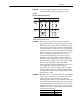
DC Motors Operation 13 Balance Motors are dynamically balanced to commercial limits unless ordered differently. Balance is done with a full length 1/2 height shaft key. A full shaft key is shipped with the motor. Sheave or coupling should be balanced with a 1/2 height shaft key. Standard Dynamic Balance Limits Highest Rated Speed (RPM) 3,000 - 4,000 1,500 - 2,999 1,000 - 1,499 Up to 999 Maximum Amplitude (Inches) 0.0010 0.0015 0.0020 0.
DC Motors In addition to observing the above precaution, all precautions (Attentions) mentioned in this document should be observed. • The armature should rotate freely and be clear of any obstructions. • The brushes should move easily in their holders and should make proper contact on the commutator. • The interior of the motor should be clean and dry. • Connections must be tight. • The driven machine should be unloaded, if possible.
DC Motors 15 Standard continuous duty DPG, TEFC and TENV stabilized shunt wound DC motors have continuous duty fields capable of continuous excitation at standstill (armature circuit not energized) under normal industrial conditions. Standard continuous duty self-ventilated motors are suitable for rated load at rated speed operation at field voltages up to 110% of rated value.
DC Motors Maintenance ! ATTENTION: Internal parts of this motor may be at line potential even when it is not rotating. Before performing any maintenance which could result in contacting any internal part, be sure to disconnect all power from the motor. Failure to observe this precaution could result in severe personal injury or death. Inspections Regular inspection at intervals dependent upon service conditions is the best insurance against costly maintenance and breakdown.
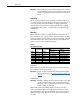
DC Motors 17 Table H Service Condition Service Condition Ambient Temperature Standard –18 to 40 degrees C (0 to 104 degrees F) Severe –30 to 50 degrees C (–22 to 122 degrees F) 1 Operating Atmosphere Hours/Day Clean 8 Bearing Load Steady Medium Shock, Vibration Medium Dirt, 8 to 24 (less than 0.2 in/sec.) Abrasives, Corrosion Heavy Shock, Vibration Heavy Dirt, 8 to 24 Extreme 2 –54 to 65 degrees C (–65 to 149 degrees F) 1 (more than 0.
DC Motors ! ATTENTION: To guard against personal injury or death from rotating parts or electrical shock, relubrication should only be performed while the motor is stationary and disconnected from the power source. 3. Remove grease drain plug located opposite the grease inlet. 4. Using a manual grease gun, pump in the recommended grease in the amount shown in Table G.
DC Motors 19 Most commonly used bearings are: • Single row, open ball bearings for coupled and belted duty for frames C210ATZ - C250ATZ. • Single row, open ball bearings for coupled duty for frames C280ATZ - C440ATZ. • Cylindrical roller bearings at drive end for belted duty on frames UC280ATZ - UC440ATZ Frequent bearing checks are recommended. If temperatures become excessive, investigate immediately for the cause. Total bearing temperatures should not exceed 90 degrees C (194 degrees F).
DC Motors 4. Rotate the rocker ring by hand 90 degrees to replace brushes located in the 12 and 6 o'clock position. 5. Return rocker to original position and change brushes in the 3 and 9 o'clock position. 6. Re-align the neutral setting mark on the rocker ring in line with the mark on the bracket boss. 7. Tighten the four hex head cap bolts which hold the rocker ring to the bracket. 8. Fit the face of new brushes to the contour of the commutator with sandpaper only, no emery abrasive.
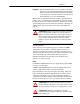
DC Motors 21 Table J Commutation Problem Quick Check Chart Symptom Identified By 1. Excessive sparking at motor or Sparking generator commutator. Possible Cause 1. Dirty or corroded commutator due to dirt, ambient contaminants, oil or oil mist, etc. 2. Brushes incorrectly seated. 3. High or feather-edged mica. 4. Faulty machine adjustment. 5. Interpoles failed or improperly adjusted. 6. Loss of brush spring tension. 7. Brushes sticking in brush holder. 8. Unit overload. 9.
DC Motors Commutation Intermittent sparking due to overloads or slight visible sparking does not necessarily indicate poor commutation. Poor commutation exists when there is excessive sparking requiring abnormal maintenance. Every case of excessive sparking should be investigated to determine the cause and correct it. Table J may help in analyzing commutation problems. DC motors and generators are brushed for full load current.
DC Motors Disassembly and Reassembly Instructions 23 The motor design incorporates many new techniques which are described in this section. It is recommended that these differences be understood thoroughly before any disassembly work is done to avoid possible damage or harm to either machine and/or maintenance personnel. Air Gap And Shimming (Frames C210ATZ - C400ATZ) Main Pole Steel or brass shims, when used, are placed between pole and frame.
DC Motors Conduit Boxes Conduit box on C210ATZ - C400ATZ is located on the frame at the commutator end. Brush Rigging and Brush Holders The brush holders are of constant pressure design and do not require nor are capable of adjustment over the life of the brushes. Bracket Re-assemblY To obtain proper planity between the integral mounting feet on the front and back end brackets. a smooth level surface should be used to align the brackets when they are assembled to the frame.
DC Motors Total Service Programs 25 Allen-Bradley can provide a wide range of maintenance programs to help you reduce downtime, improve productivity and increase profits. Capabilities include: • Motor Start-up Service • Motor Electrical and Mechanical Preventive Maintenance • Vibration Analysis • Mobile Van Repair Service • Balancing and Alignment Service • Maintenance Service • 24-Hour Technical Support • Modernization Service For more information contact your local Allen-Bradley Sales Office.
Notes DC Motors
DC Motors Notes 27
Online Documentation The latest motor information can be obtained from the Allen-Bradley Drives & Motors home page on the World Wide Web at: http://www.ab.com/drives/motors Publication 1325L-UM002A-EN-P – August, 2001 Supersedes 1325L-5.0 dated March, 1999 Copyright © 2001 Rockwell Automation. All rights reserved. Printed in USA.