Input RFI Filters User Manual
Instructions Input RFI Filters The Input RFI Filter units are designed to be used with the following Allen-Bradley Adjustable Frequency AC Drives: • • • • • 1305 1336 PLUS 1336 PLUS II 1336 FORCE™ 1336 IMPACT™ The main function of the input RFI filter is to reduce the radio frequency conducted emissions into the main supply lines and ground wiring. This publication provides the steps needed to install the filter.
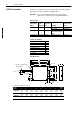
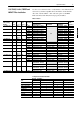
2 Input RFI Filters 1305 Filter Installation Use the cross reference below to verify that the correct filter and kit have been selected for your CE compatible drive. Important: Do not use the filters listed below in single-phase applications. Consult factory for further information. Filter Selection Power Three-Phase Dissipation Volts Used with . . . 4.2 Watts 200-240V 1305-AA02A, AA03A 1305-AA04A 1305-RFB-08-B 8.8 Watts 200-480V 1305-AA08A, BA01A, BA02A, BA03A, BA04A, BA06A 1305-RFB-12-C 10.
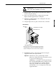
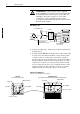
Input RFI Filters ! 3 ATTENTION: To prevent electrical shock, disconnect the power source before installing or servicing. 1. Mount the filter to the panel. Refer to the Dimension drawing shown on the previous page. 2. Remove and discard the plastic conduit panel of the 1305. Replace with the supplied metal conduit panel. 3. Mount the grounding bracket to the conduit panel of the drive using the supplied hardware.
4 Input RFI Filters ! ATTENTION: To guard against possible equipment damage, RFI filters can only be used with AC supplies that are nominally balanced with respect to ground. In some installations, three-phase supplies are occasionally connected in a 3-wire configuration with one phase grounded (Grounded Delta). The filter must not be used in Grounded Delta supplies.
Input RFI Filters 1336 PLUS, PLUS II, FORCE and IMPACT Filter Installation 5 Use the cross reference below to verify that the correct filter has been selected for your CE compatible drive. In addition, ensure that the drive was ordered with the “-AE” enclosure option or the EMC Enclosure Kit (1336x-AEx) has been properly installed.
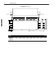
6 Input RFI Filters Filter Dimensions TB Cover = 50.0 (1.97) x 41.0 (1.61) x 66.0 (2.60) B E H 6.5 (0.26) Braided Shield A D 100.0 (3.94) 10.0 (0.39) 10.0 (0.39) English F C 1.0 (0.04) All Dimensions in Millimeters and (Inches) Catalog Number 1336-RFB-7-AA 1336-RFB-16-AA 1336-RFB-30-A A 50.0 (1.97) 55.0 (2.17) 60.0 (2.36) B 255.0 (10.04) 305.0 (12.00) 335.0 (13.19) C 126.0 (4.96) 142.0 (5.59) 160.0 (6.30) D 25.0 (0.98) 30.0 (1.18) 35.0 (1.38) E 240.0 (9.45) 290.0 (11.42) 320.0 (12.60) F 180.
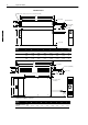
Input RFI Filters 7 Filter Dimensions (continued) Conduit Fitting C H A D English H E F G B Catalog Number 1336-RFB-30-A4 1336-RFB-27-B 1336-RFB-48-B 1336-RFB-80-C A 260.1 (10.24) 276.6 (10.89) 276.6 (10.89) 302.0 (11.89) B 413.7 (16.29) 540.0 (21.26) 540.0 (21.26) 775.0 (30.50) C 58.0 (2.28) 58.0 (2.28) 68.1 (2.68) 78.5 (3.09) D 230.1 (9.06) 212.6 (8.37) 212.6 (8.37) 238.0 (9.37) E 320.0 (12.60) 461.0 (18.15) 461.0 (18.15) 685.8 (27.00) F 15.0 (0.59) 10.9 (0.43) 10.9 (0.43) 20.4 (0.
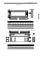
8 Input RFI Filters Filter Dimensions (continued) 122.0 (4.08) 122.0 (4.08) English F B H E E E F C A D 5.0 (0.20) Dia. Ground Stud G Catalog Number 1336-RFB-475-G 1336-RFB-590-G 1336-RFB-670-G A 300.0 (11.81) B 794.0 (31.26) C 160.0 (6.30) D 275.0 (10.83) E 200.0 (7.87) F 70.0 (2.76) G 12.5 (0.49) H 740.0 (29.13) Weight kg (lbs.) 29.0 (63.
Input RFI Filters ! 9 ATTENTION: To prevent electrical shock, disconnect the power source before installing or servicing. 1. Perform the appropriate step below (A, B, C, D or E) to mount the filter and drive. A. 1336-RFB-7-AA, 16-AA, 30-A Filters Mount the filter and drive to the panel. See the Dimension & Mounting diagrams provided in this document. Drive mounting information can be found in the User Manual. Important: Hardware must be installed as shown in the Mounting diagram on page 11. C.
10 Input RFI Filters 2. The RFI filter must be connected between the incoming AC supply line and the drive input terminals. Important: The filter may cause ground leakage currents. Therefore a solid ground connection must be provided as shown below. Remove the filter access panel (or terminal block cover) to expose the input terminal block. Connect the incoming AC lines (see note 1) to the appropriate terminals on the block ("Line/L1, L2, L3"). Replace access panel/cover.
Input RFI Filters 11 Filter Mounting Series B Filters can be mounted using either method Important: A positive electrical bond must be maintained between drive and filter at all 4 corners. Star washers can be eliminated if a positive electrical bond is assured. Important: Drive and filter must be mounted to a common back plane with a positive electrical bond and in close proximity to one another.
12 Input RFI Filters Filter Mounting (continued) Important: Drive and filter must be mounted to a common back plane with a positive electrical bond. Spacing is determined by Conduit Box.
Input RFI Filters 13 Filter Mounting (continued) Important: A positive electrical bond must be maintained between the enclosure and filter (including brackets), fans, and drive. To assure a positive electrical bond, any paint near all mounting points must be removed. All Dimensions in Millimeters and (Inches) Important: Cooling fans are required for proper drive operation. Fans and air intake openings must be EMI shielded. Refer to the drive User Manual for CFM recommendations. 75.0 (2.
14 Input RFI Filters 1336 PLUS, PLUS II, FORCE & IMPACT Knockout Definitions Dimensions are in Millimeters and (Inches) Frames A1 through A4 Control I/O Motor Output Filter Input Control I/O Frames B and C Filter Input Motor Output SCANport English SCANport 22.2/28.6 (0.88/1.13) - 3 Plcs. 28.6/34.9 (1.13/1.38) - 3 Plcs. 22.2 (0.88) - 1 Plc. Frame E Frame D Filter Input 22.2 (0.88) - 1 Plc.
Publication RF-101ML-EN – December, 1999 Supersedes July, 1999 P/N 74103-446-01 (06) Copyright 1999 Rockwell International Corporation. All rights reserved. Printed in USA.