
Reference Guide Owner manual

Rockwell Automation Publication 1305-5.2.2 - September 2013 3
1305 Adjustable Frequency AC Drive
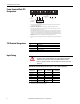
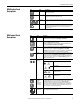
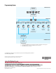
Terminal Block TB2
Designations
See footnotes below.
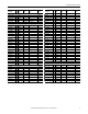
TB2 Terminal Descriptions
➀ Required to operate drive. STOP also used to clear a fault.
➁ Use HIM Stop button to clear faults.
➂ Contact Closure Input. Internal 5V supply. Do not apply external voltage.
➃ When the ENABLE signal is lost, the drive output immediately shuts off and the motor will coast to a stop.
➄ A Start command will override any Jog command.
➅ See 1305 User Manual, publication 1305-5.2, for input configurations based on the setting of parameter 21 - [Input Mode].
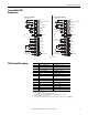
Remote Pot
1
2
3
4
5
6
7
8
9
10
Source
Wiper or 0-10V DC Input
Common
4-20mA Input
0-10V Output
0-10V
Common
Stop
➂
Start
➂
Output #1
➄
➀➃
➀
24VDC Source
(User Supplied)
11
12
13
14
15
16
17
18
19
20
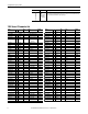
Enable
➂
Common
Reverse
➂
Jog
➂
Common
SW2
➂➅
SW3
➂➅
SW1
➂➅
(Sink)
Output #2
User Side
Remote Pot
Run Forward
Run Reverse
Jumper
➀➁
Jumper
➀➃
1
2
3
4
5
6
7
8
9
10
Source
Wiper or 0-10V DC Input
Common
4-20mA Input
0-10V Output
0-10V
Common
Stop
➂
User Side
Start
➂
Output #1
24VDC Source
(User Supplied)
11
12
13
14
15
16
17
18
19
20
Enable
➂
Common
Reverse
➂
Jog
➂
Common
SW2
➂➅
SW3
➂➅
SW1
➂➅
(Sink)
Output #2
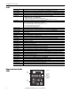
General Three Wire General Run Fwd/Rev
Terminals Signal Specification
1, 2, 3 External Speed Potentiometer 10 kΩ Potentiometer, 2 watts
2, 3 0…10V Analog Input Drive Input Impedance = 100 kΩ
4, 3 4…20 mA Analog Input Drive Input Impedance = 250 Ω
5, 3 0…10V Analog Output Meter Impedance ≥ 4 kΩ
6, 7 Start Contact Closure Input ➂
8, 7 Stop Contact Closure Input ➂
9, 10 Programmable Output 1 Resistive Rating = 115V AC/30V DC, 5A
Inductive Rating = 115V AC/30V DC, 2A
11, 12 Drive Enable Contact Closure Input ➂ ➃
13, 12 Reverse Contact Closure Input ➂
14, 15 Jog Contact Closure Input ➂
16, 15 SW1 Contact Closure Input ➂
17, 15 SW2 Contact Closure Input ➂
18, 15 SW3 Contact Closure Input ➂
19, 20 Programmable Output 2 24V DC ± 20%, 50 mA max (sink)