
Owner's manual

Chapter 5 –Programming
5-21
Advanced Set Up Group (cont.)
[
Analo
g
In
v
er
t]
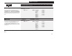
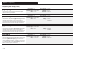
Parameter # 84 Factory Default ‘‘Disabled”
[
Analo
g
In
v
er
t]
Parameter Type Read & Write
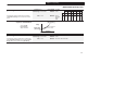
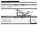
This parameter enables the inverting function for the 0-10
Volt an
d
4-20mA analog in
pu
t
s
ignal at
T
B2.
Units None Settings ‘‘Enabled”
Maximum Input Commands [Minimum Freq]
Minimum Input Commands [Maximum Freq]
Volt an
d
4-20mA analog in
pu
t
s
ignal at
T
B2.
‘‘Disabled”
Maximum Input Commands [Maximum Freq]
Minimum Input Commands [Minimum Freq]
Figure 5.12 Analog Invert
[Maximum Frequency] '
0 V
4 mA
Drive Output
y
10 V
20 mA
y
[Minimum Frequency]
'
Disabled
Enabled
[
4-2
0m
A
Lo
ss
Sel
]
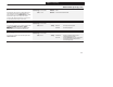
Parameter # 81 Factory Default ‘‘Stop/Fault”
[
4-2
0m
A
Lo
ss
Sel
]
Parameter Type Read & Write
This parameter selects the drives reaction to a loss of a
seevere en y So r e s
Units None Settings ‘‘Stop/Fault”
Drive Stops and Issues ‘‘Hz Err Fault” (F29)
T s p r e er se e s e dr ves re ss
4-20mA signal when the active [Frequency Source] is
IMPO TA T: T e drve u pu s e
‘‘Hold/Alarm”
Drive Maintains Last Output Freq and sets an Alarm bit
4-20mA.
IMPO
R
TA
N
T:
T
h
e
dr
i
ve
o
u
t
pu
t contact
s
can b
e
used to issue an alarm signal by setting [Output 1 Config]
r Op 2on r IMPO TA T: ss
‘‘Max/Alarm”
Drive Outputs [Maximum Freq] and sets Alarm bit
used
to i
ssue
an ala
r
m
s
ignal by
se
tting [
O
ut
p
ut 1 C
on
fig]
or [Output 2 Config] to “alarm”. IMPORTANT: Loss of
s s de ed s s r s
‘‘Pre1/Alarm”
Drive Outputs [Preset Freq 1] and sets an Alarm bit
s
ignal i
s
de
fin
ed
a
s
a
s
ignal < 3.5 mA o
r
a
s
ignal >
20.5 mA.
‘‘Min/Alarm”
Drive Outputs [Minimum Freq] and sets an Alarm bit