
Owner manual


Index
I–2
Publication 1302-5.0 – January, 1998
Grounding, 5–10
Humidity, A–1
IET reset, digital input, 5–7
IGBT power devices
checking, 9–8
Input, AC, 2–2
Jumper (J6)
location of, 4–6
Lead lengths, motor, 3–6
LED descriptions, 7–3
Line frequency, A–1
Line noise, avoiding, 4–5
Manual Torque Boost (F06), 8–7
Maximum Speed (F04), 8–6
Mechanical motor overload protection, 4–5
Membrane switch/bracket assembly, 2–8 &
2–9
Minimum Speed (F03), 8–5
Model numbers, 2–6
Monitor mode, 7–6
Motor
lead lengths, 3–6
multiple motor applications, 3–6 & 3–9
overload protection, mechanical, 4–5
single motor applications, 3–6 & 3–9
Mounting dimensions, 3–3
Multi–Speed Presets 1,2,3 (F–23, F–24,
F–25), 8–17
Multi–Speed presets, digital inputs, 5–6
NEMA enclosures, 2–7
Option kits, 2–7
Output
current, 2–8
power wiring, 5–10
status relay wiring, 5–9
Parameters
displaying or changing values, 8–1
factory settings and defaults, B–1
listed alphabetically, C–1
menu structure, 7–5
password protection, 8–2
record of user settings, D–1
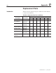
Parts, replacement, D–1
Password protection, 8–2
Percent Selected Speed Reference Display
Enable (F–13), 8–11
Planning
drive clearance 3-2&3-4
location, 3–2 & 3–4
Power
loss ratings, 3–2, 3–4
wire sizes, 3–2 & 3–4
Power Module
checking circuitry with power off, 9–7
Power Up Start Enable (F19), 8–14
Program mode, 8–1
Ratings
AC input, 2–3
NEMA, 2–7
power, 2–1
power loss, 2–1
Regulator Board, 2–5
Remote Reference Gain (F–11),8-10
Remote Reference Offset (F–12),
Replacement parts,D-1
Reset, digital input, 5–5