
Owner manual

Technical SpecificationsA–2
Publication 1302-5.0 — January, 1998
)
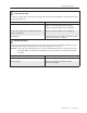
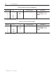
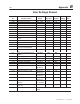
Table A.D - Drive Inputs
Analog Speed Reference 0 to 10ĂVDC or 0 to 20ĂmA
Start EdgeĆsensitive signal that must see an openĆtoĆclosed contact
transition. This transition may be a momentary or fixed closure.
Stop An open contact that must be closed when the Drive is running.
The Drive will remain off as long as the contact is open.
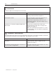
IET Reset EdgeĆsensitive signal that must see an openĆtoĆclosed contact
transition. This transition may be a momentary or fixed closure.
Forward/Reverse An open contact to assert the forward direction and a closed
contact to assert the reverse direction.
Function Loss An open contact that must be closed when the Drive is running.
When the contact is open, the Drive turns off. The Drive will remain
off as long as the contact is open.
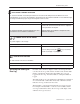
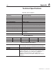
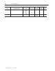
Table A.E - Drive Outputs
Analog Output
(0Ć10ĂVDC scaled signal)
The scaled signal is selected through parameter FĆ29 and can be
one of the following:
D Output Voltage: 0 to 632 VAC
D % Load (Amps): 0 to 200% (Percentage of output amps
based on the Drive nameplate.)
D RPM/Engineering Unit: Minimum to maximum RPM or
minimum to maximum of any
engineering unit (See parameter
FĆ08)
D % Selected Speed Reference: 0 to 100% (Percentage of
the selected reference
signal range.)
Snubber Resistor Braking Snubber resistor control signal used by an optional snubber
resistor.
Output Status Relay 115 VAC/24 VDC, 0.5 Amp, relay output (One Form A and one
Form B contact wired with a single common.)