
Owner manual

9–2 Troubleshooting
Publication 1302-5.0 — January, 1998
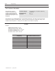
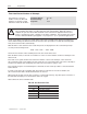
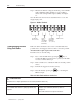
Step 4. Measure the DC bus voltage at the DC bus power terminals
with a multimeter while standing on a non-conductive
surface and wearing insulated gloves (600V). See Figure
9.1.
Once the Drive has been serviced, reattach the Drive’s cover and
reapply input power.
Figure 9.1 - DC Bus Terminals
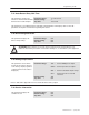
Table 9.A defines the fault codes for user-correctable faults, lists
possible causes, and suggests actions to take to correct the problem.
All other faults require replacement of the drive.
If a fault occurs, do the following:
Step 1. Try to clear the fault first by pressing the
STOP
RESET
key or
asserting the IET reset input (remote operation). If the fault
reoccurs, continue with step 2.
Step 2. Refer to Table 9.A to identify the fault code and the possible
causes.
Step 3. Perform the suggested corrective action(s).
Step 4. Clear the fault by pressing the
STOP
RESET
key or asserting the
IET reset input.
Table 9.A - Drive Faults and Corrective Actions
= FUNCTION LOSS
Possible Cause Corrective Action
!
!
"
Trouble
s
hooting
the
Drive
Using Fault Codes