
Owner manual

5–7Drive Wiring
Publication 1302-5.0 — January, 1998
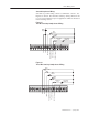
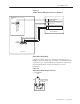
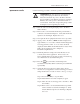
Figure 5.8
Terminal Usage During Multi–Speed Preset Operation
FĆ00=0,1,2
FĆ00 = 3 (MultiĆSpeed Presets)
$"%$!%$
$ !
$"$
#$
"'"&"#
%$ ##
%"##$ "
"
$"%$!%$
$"$$ !#$
%$(!"#$
%$(!"#$
"'"&"#
%$ ##
%"##$ "
"
IET Reset Control Wiring
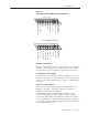
IET reset control wiring connects to terminals 8 and 11. See Figures
5.5 and 5.6. Note that these reset wiring connections are not to be
used in multi-speed preset applications. See Figures 5.7 and 5.8.
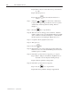
Forward/Reverse Control Wiring
Forward/reverse control wiring connects to terminals 9 and 11. See
Figures 5.5 through 5.7. Note that the setting of the forward/reverse
switch is ignored when parameter F-17 is equal to 1 (disable reverse
operation).
Function Loss Control Wiring
Function loss control wiring connects to terminals 10 and 11. See
Figures 5.5 through 5.7. Typically, a function loss input is a
maintained, normally-closed pushbutton.
A signal must be present at terminal 10 for the Drive to run. A
factory-installed jumper connects terminals 10 and 11 which
provides that signal. Remove this jumper if a function loss input, a
coast-stop pushbutton, or another external interlock (for example, a
motor thermostat) is used. Removing the jumper allows the Drive to
stop when the contact is open.