
Owner manual

5–4 Drive Wiring
Publication 1302-5.0 — January, 1998
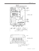
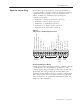
Table 5.3
Analog Speed Reference Wiring Connections
Ω
"!%$
!
###!
%
!
%
"!%$
!
$#
!
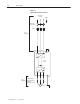
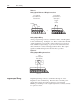
Analog Output Wiring
Analog output wiring connects to terminals 4 and 5 on the Regulator
board’s terminal strip. See Figure 5.4. This is a scaled 0 to 10 VDC
output signal that is proportional to either current speed, percent of
load, calculated output voltage, or percent of the selected reference
value, whichever is selected through parameter F-29. This output
signal is available during both local and remote operation.
Figure 5.4
Analog Output Wiring Connections
"!%$
#!
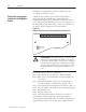
Digital input wiring connects to terminals 6 through 11 on the
Regulator board’s terminal strip. The Drive has a 24 VDC power
supply that provides the required voltage for control signals.
Enabling or disabling a control signal requires that a contact (switch)
be opened or closed.
Digital
Input
W
iring