
Owner manual

5–3Drive Wiring
Publication 1302-5.0 — January, 1998
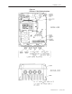
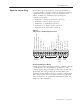
The Terminal strip on the Regulator board provides terminals for
connecting signal (for example, external speed reference and analog
output) and control (for example, stop, start, and function loss)
wiring. See Figure 5.2. Terminals for the following wire
connections are provided:
• Terminals 1–3: analog speed reference connections
• Terminals 4–5: analog output connections
• Terminals 6–11: digital input connections
• Terminals 12–13: snubber resistor connections
• Terminals 14–16: output status connections
Table 5.2
Typical Control Terminal Strip Connections
Analog
Speed
Reference
Analog
Output
Digital
Inputs
Snubber
Resistor
Braking
Signal
Output
Status
Relay
Isolated Reference Voltage
Voltage/Current Speed Reference
Isolated Reference Ground
Analog Meter Output
24 VDC Common
Stop
Start
Reset
Forward/Reverse
Function Loss
24 VDC Common
Snubber Resistor Braking Signal
24 VDC Common
Relay Common
N.O. Relay Contact
N.C. Relay Contact
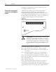
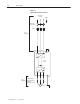
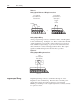
Analog Speed Reference Wiring
Analog speed reference input wiring connects to terminals 1 through
3 on the Regulator board’s teminal strip. See Figure 5.3. This
reference signal is jumper-selectable for either a 0 to 10 VDC or 0 to
20 mA input. The setting of jumper J6 on the Regulator board
determines whether the input reference is a voltage or current signal.
This reference signal can be provided by either a user-supplied 5K
ohm potentiometer or an external 0-10 VDC/0-20 mA supply. See
Chapter 4 for more information.
S
ignal
and
Control
W
iring