302 AC Drive (575V AC) Version 3.
Important User Information Solid state equipment has operational characteristics differing from those of electromechanical equipment. “Safety Guidelines for the Application, Installation and Maintenance of Solid State Controls” (Publication SGI-1.1) describes some important differences between solid state equipment and hard–wired electromechanical devices.
Table of Contents Introduction Chapter 1 Manual Objectives . . . . . . . . . . . . . . . . . . . . . . . . . . . . . . . . . . . . Drive Description Chapter 2 Introduction . . . . . . . . . . . . . . . . . . . . . . . . . . . . . . . . . . . . . . . . . Standard Features . . . . . . . . . . . . . . . . . . . . . . . . . . . . . . . . . . . . Drive Description . . . . . . . . . . . . . . . . . . . . . . . . . . . . . . . . . . . . . System Diagram . . . . . . . . . . . . . . . . . . . . . . . . . . . . .
ii Table of Contents Final Installation Checks Chapter 6 Introduction . . . . . . . . . . . . . . . . . . . . . . . . . . . . . . . . . . . . . . . . . Power Off Checks . . . . . . . . . . . . . . . . . . . . . . . . . . . . . . . . . . . . Operational Checks . . . . . . . . . . . . . . . . . . . . . . . . . . . . . . . . . . . Display and Keypad Operation Chapter 7 Programming Chapter 8 Introduction . . . . . . . . . . . . . . . . . . . . . . . . . . . . . . . . . . . . . . . . .
Chapter 1–1 1 Introduction Manual Objectives The purpose of this manual is to provide you with the necessary information to install, program, start up and maintain the 1302 AC Drive. This manual should be read in its entirety before operating, servicing or initializing the 1302 Drive. This manual is intended for qualified electrical personnel responsible for installing, programming, starting up, and maintaining the 1302 drive. This manual describes how to install and troubleshoot the 1302 AC drive.
1–2 Introduction ! ATTENTION: Only qualified electrical personnel familiar with the construction and operation of this equipment and the hazards involved should install, adjust, operate and/or service this equipment. Read and understand this section in its entirety before proceeding. Failure to observe this precaution could result in bodily injury or loss of life. ATTENTION: An incorrectly installed or applied Drive can result in component damage or a reduction in product life.
Chapter 2–1 2 1302 AC Drive Description Introduction This chapter describes the 1302 Drive and how to identify it based on its model number. This chapter also provides power and enclosure rating information.
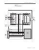
2–2 1302 AC Drive Description Drive Description The 1302 Drive is an AC PWM (pulse–width–modulated) inverter that operates on single–or three–phase power as detailed in Figures 2.1 and 2.2. AC input power is applied to the Drive’s input terminals. Voltage transients are suppressed by three metal-oxide-varistor (MOV) suppressors. These suppressors keep any input voltage transients within the maximum voltage rating of the input diode module.
1302 AC Drive Description 2–3 Figure 2.1 1302 System Diagram DIODE MODULE IGBT MODULE DC CT LINE INPUT 575VAC R AC Induction U Motor S T + V W TO OPTIONAL SNUBBER RESISTOR + – 10 VDC + – 10 VDC COMMON 24 VDC 24 VDC COMMON +15 VDC –15 VDC TO FIG 2.2 J4 BUS VOLT FEEDBACK POWER SUPPLY BUS CURRENT FEEDBACK +5 VDC REGULATOR COMMON GATE SIGNALS Publication 1302-5.
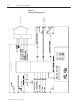
2–4 1302 AC Drive Description Publication 1302-5.0 — January, 1998 Figure 2.2 1302 System Diagram Cont.
1302 AC Drive Description 2–5 Figure 2.3 Regulator Board Component Locations % % % % % % % % % $ $ $ $ $ $ ! " & ! # & Publication 1302-5.
2–6 1302 AC Drive Description Model Numbers A model number identifies each 1302 AC Drive as detailed in Table 2.A. This number appears on the shipping label and on the Drive’s nameplate located on the right side of the Drive housing. The Drive’s model number contains codes that indicate: input voltage range, enclosure rating, and horsepower rating. Drive enclosure ratings are detailed later in this chapter. All 1302 Drives described in this instruction manual function in the same manner. Table 2.
02 AC Drive Description 2–7 Enclosure Ratings Each 1302 Drive has one of the following ratings: Table 2.B - 1302 NEMA Ratings NEMA Rating 1 4X/12 12 Description Vented. For generalĆpurpose indoor applications. Not vented. Supplied with base and keypad gaskets. For use in indoor environments that require a waterĆtight and dustĆtight enclosure. An enclosure with this NEMA rating encompasses both ratings (4X and 12).
2–8 1302 AC Drive Description Figure 2.4 Enclosure B Component Locations CONTROL TERMINAL STRIP REGULATOR PCB MEMBRANE SWITCH/ BRACKET ASSEMBLY INTERNAL FAN ASSEMBLY CAPACITOR PCB (3&5 HP ONLY) POWER PCB GND CONNECTION POWER TERMINAL STRIP Publication 1302-5.
1302 AC Drive Description 2–9 Figure 2.5 Enclosure C Component Locations CONTROL TERMINAL STRIP REGULATOR PCB MEMBRANE SWITCH/ BRACKET ASSEMBLY INTERNAL FAN ASSEMBLY POWER TERMINAL STRIP CAPACITOR PCB GND CONNECTIONS POWER PCB Publication 1302-5.
2–10 1302 AC Drive Description This Page Intentionally Blank Publication 1302-5.
1302 AC Drive Description 2–11 Publication 1302-5.
2–12 1302 AC Drive Description Table 2.A 1302 Model Number Notation Model Number 1.5 2 3 5 7.5 10 15 20 25 30 40 50 60 75 100 125 150 Input Voltage 6.2 Nm (55 lb-in) 6.2 Nm (55 lb-in) 6.2 Nm (55 lb-in) 6.2 Nm (55 lb-in) 6.2 Nm (55 lb-in) 6.2 Nm (55 lb-in) 13.6 Nm (120 lb-in) 13.6 Nm (120 lb-in) 13.6 Nm (120 lb-in) 13.6 Nm (120 lb-in) 22 Nm (200 lb-in) 22 Nm (200 lb-in) 22 Nm (200 lb-in) 22 Nm (200 lb-in) — — Horsepower — — 6.2 Nm (55 lb-in) 6.2 Nm (55 lb-in) 6.2 Nm (55 lb-in) 6.2 Nm (55 lb-in) 6.
Chapter 3–1 3 1302 Preinstallation General Chapter 3 provides information that you must use when planning a 1302 AC Drive installation. Installation site, wiring and motor application requirements are included in this chapter. ! ! ATTENTION: The following information is merely a guide for proper installation. The National Electrical Code and any other governing regional or local code will overrule this information.
3–2 1302 Preinstallation Site Requirements It is important to properly plan before installing a 1302 Drive to ensure that the Drive’s environment and operating conditions are satisfactory. Note that no devices are to be mounted behind the Drive. This area must be kept clear of all control and power wiring. Read the following recommendations before continuing with the Drive installation.
1302 Preinstallation 3–3 Figure 3.1 Enclosure B Dimensions Figure 3.2 Enclosure C Dimensions Publication 1302-5.
3–4 1302 Preinstallation Cooling Airflow Be sure there is adequate clearance for air ventilation around the Drive. For best air movement, do not mount 1302 Drives directly above each other. Note that no devices are to be mounted behind the Drive. This area must be kept clear of all control and power wiring. See Table 3.A for a listing of the recommended air flow clearances. Table 3.
1302 Preinstallation 3–5 Table 3.B - Recommended Power Wire Sizes Type of Wiring Terminals Size of Wire (maximum)* AC Input Power R(L1), S(L2), T(L3) 14 AWG, 2 (mm2) Output Power U(T1), V(T2), W(T3) 14 AWG, 2 (mm2) DC Bus ć,+ 14 AWG, 2 (mm2) Snubber Resistor +10 VDC, 10 COM 14 AWG, 2 (mm2) Ground GND 14 AWG, 2 (mm2) Table 3.C - Recommended Power Terminal Tightening Torque Drives Terminals Maximum Tightening Torque All All power wires 1.08 NewtonĆmeters (9.
3–6 1302 Preinstallation Recommended Motor Lead Lengths The following motor lead lengths are recommended to reduce line disturbances and noise. See Figure 3.3. • For applications using one motor, motor lead length should not exceed 76 meters (250 feet). • For applications with multiple motors, total motor lead length should not exceed 76 meters (250 feet). When total lead length exceeds 76 meters (250 feet), nuisance trips can occur, caused by capacitive current flow to ground.
1302 Preinstallation 3–7 Table 3.E Maximum Motor Cable Length Restrictions in meters (Feet) for 1302 No External Devices Motor A w/ Reactor/Filter at Drive Motor Motor 1329R A B 1329R A B 1329R Any Cable Any Cable Any Cable Any Cable Any Cable Any Cable Any Cable NR 121.9 (400) 152.4 (500) NR NR NR 121.9 (400) 152.4 (500) 2.2 (3) NR NR NR 152.4 (500) 304.8 (1000) 152.
3–8 1302 Preinstallation Table 3.F- AC Input Line Fuse Selection Values Model Number Fuse Rating* 1302–C001–AA 4A 1302–C001–AF 4A 1302–C002–AA 7A 1302–C002–AF 7A 1302–C003–AA 10A 1302–C003–AF 10A 1302–C004–AA 15A 1302–C005–AA 15A 1302–C005–AF 20A 1302–C007–AF 20A 1302–C010–AA 25A 1302–C010–AF 25A Emergency Stop Installation ! ATTENTION: The 1302 Drive control circuitry includes solid state components.
1302 Preinstallation 3–9 The required external hardwired emergency stop must be either a category 0 or 1 stop, depending on the user’s risk assessment of the associated machinery. In order to fully comply with machinery safety standard EN 60204-1:1992, part 9.2.5.4, at least one of the two stop methods must be a category 0 stop.
3–10 1302 Preinstallation The sum of the maximum full-load sine wave currents of all the motors connected continuously to the Drive must be less than the maximum output current rating under all conditions. Note that each motor requires separate thermal overload protection (for example, a motor relay or a motor thermostat). Publication 1302-5.
Chapter 4–1 4 Installation Introduction This chapter shows how to mount the 1302 Drive and its external components. Also shown are the entry areas for routing wiring in and out of the Drive. Mounting the Drive Attach the drive to the selected flat, vertical surface using the mounting holes provided. Enclosure B and C Drives have four mounting holes. In order to maintain a flat mounting surface and to ensure that bolt tightness is maintained, use washers under the bolt heads. Refer to Figures 3.
4–2 Installation Figure 4.1 Enclosure B Wire Routing Locations Publication 1302-5.
Installation 4–3 Figure 4.2 Enclosure C Wire Routing Locations Publication 1302-5.
4–4 Installation External Component Installation Install the input power and output power components that are located outside of the 1302 enclosure. See Figure 5.1. The following sections describe disconnect, transformer, and AC line branch protection installation Disconnects An input disconnect (for example, a switch or circuit breaker) must be installed in the line before the Drive input terminals in accordance with local, national, and international codes (e.g., NEC/CEC).
Installation 4–5 Input isolation transformers may be needed to help eliminate the following: • • • Damaging line voltage transients. Line noise from the Drive back to the incoming power source. Damaging currents that could develop if a point inside the Drive becomes grounded. Observe the following guidelines when installing an isolation transformer: • • A power disconnecting device must be installed between the power line and the primary of the transformer.
4–6 Installation In multiple motor applications, each motor must have its own user-supplied overload protection. Setting the Analog Input Jumper on the Regulator Board 1302 Drives have an analog speed reference input. This is a jumper-selectable 0 to 10 VDC or 0 to 20 mA input with programmable gain and offset adjustments (parameters F-11 and F-12). Jumper J6 on the Regulator board is set to match the type of incoming analog signal, either voltage or current. See Figures 2.2, 4.3, and 5.3.
Installation 4–7 Motor Preparation Follow these guidelines when preparing to install the motor: • Verify that the motor is the appropriate size to use with the Drive. • Verify that the total motor lead length does not exceed the values given in Chapter 3. • Follow the instructions in the motor instruction manual when installing the motor. • Verify that the motor is properly aligned with the application’s machine to minimize unnecessary motor loading due to shaft misalignment.
4–8 Installation This Page Intentionally Blank Publication 1302-5.
Chapter 5–1 5 Drive Wiring Introduction This chapter describes how to wire the 1302 Drive including: input wiring, control and signal wiring, output wiring, and grounding. Input Power Wiring Use the following steps to connect AC input power to the Drive: Step 1. Verify that the AC input power to the Drive corresponds to the drive’s nameplate voltage and frequency. Step 2. Wire the AC input power leads by routing them according to the type of enclosure. Sees Figures 4.1 and 4.2 and Table 3.
5–2 Drive Wiring Table 5.1 Typical Electrical Connections AC Input Voltage GND Manual Disconnect Fuse UserĆ Supplied R/L1 S/L2 T/L3 ~ - GND 1302 Drive U/T1 Motor Overload UserĆ Relay (Optional if Supplied Electronic Overload is Used) ũ Ũ ~ V/T2 W/T3 ũ Ũ M Publication 1302-5.
Drive Wiring 5–3 The Terminal strip on the Regulator board provides terminals for connecting signal (for example, external speed reference and analog output) and control (for example, stop, start, and function loss) wiring. See Figure 5.2.
5–4 Drive Wiring Table 5.3 Analog Speed Reference Wiring Connections " !% $ ! $# " !% $ ! # # # ! % ! % Ω ! Analog Output Wiring Analog output wiring connects to terminals 4 and 5 on the Regulator board’s terminal strip. See Figure 5.4.
Drive Wiring 5–5 Start and Stop Control Wiring Start and stop control wiring connects to terminals 6, 7, and 11. See Figures 5.5 and 5.6. Note that these start/stop wiring connections are not to be used in multi-speed preset applications which are discussed in the following section. Figure 5.5 Two–Wire Start/Stop Sample Control Wiring Figure 5.
5–6 Drive Wiring Multi–Speed Preset Wiring Multi-speed preset wiring connects to terminals 6 through 8, and 11. See Figure 5.7. When control type 3 is selected through parameter F-00, remote terminal strip control is enabled with multi-speed presets. This mode of operation changes the functionality of terminals 6 through 8 and may be used in place of 2- and 3-wire start/stop wiring. See Figure 5.8.
Drive Wiring 5–7 Figure 5.
5–8 Drive Wiring ! ATTENTION: The 1302 control circuitry includes solid state components. You must provide an additional hardwired stop circuit to remove AC line power to the Drive in the case of improper operation. Failure to provide a hardwired emergency stop could result in equipment damage, bodily injury or death. When AC input power is removed, there will be a loss of inherent regenerative braking effect and the motor will coast to a stop.
Drive Wiring 5–9 Figure 5.9 Snubber Resistor Wiring Connections for 1302 Drives REGULATOR BOARD 24 VDC COMMON 12 13 SNUBBER RESISTOR BRAKING SIGNAL CONTROL TERMINAL STRIP +1 -2 POWER TERMINAL STRIP SNUBBER RESISTOR BRAKING SIGNAL +147 -45 DC BUS VOLTS +13 -14 10V SUPPLY SNUBBER RESISTOR + - + DC BUS 10V 10V VOLTS COM SP500 DRIVE Output Status Relay Wiring Output status wiring connects to terminals 14 through 16 on the Regulator board’s terminal strip. See Figure 5.10.
5–10 Drive Wiring Output Power Wiring Use the following steps to connect AC output power wiring from the Drive to the motor: Step 1. Wire the AC output power leads by routing them according to the type of enclosure. See Figures 4.1 and 4.2. See Table 3.B for recommended wire sizes. ! ATTENTION: Do not route signal and control wiring in the same conduit with power wiring. This can cause interference with Drive operation.
Chapter 6–1 6 Final Installation Checks Introduction Chapter 6 provides a guide to help you run a final check of the 1302 Drive installation. ! Power Off Checks ATTENTION: Only qualified personnel familiar with the 1302 Drive and associated machinery should perform troubleshooting or maintenance functions on the Drive. Failure to comply may result in personal injury and/or equipment damage.
6–2 Final Installation Checks Step 5. Verify that the user–installed stop pushbutton is wired correctly. Make certain the factory–installed jumper at terminals 10 and 11 has been removed so that the coast–stop pushbutton will work (Refer to Chapter 5). ! ATTENTION: Check that electrical commons are not intermixed in the Drive. Failure to observe this precaution could result in damage to, or destruction of, the Drive or process equipment. Step 6. Remove any debris from around the Drive. Step 7.
Final Installation Checks 6–3 Operational Checks Use the following procedure to check the operation of the Drive: ! ATTENTION: DC bus capacitors retain hazardous voltage after input power has been disconnected. Disconnect and lock out power to the Drive and wait five (5) minutes for the DC bus capacitors to discharge. Failure to disconnect power could result in death or serious injury. Verify bus voltages using the procedure in Chapter 9 before beginning any checks. Step 1.
6–4 Final Installation Checks Step E. Reverse any two of the three motor power leads (U, V, or W). Step F. Turn the power on. Step G. Press the rotation. key and verify the direction of Step 8. Using the and keys, run the motor without any load across the speed range. If the motor does not operate satisfactorily, check the parameter settings. Refer to Chapter 8. Step 9. Press the key to stop the Drive. Step 10. Turn off, lock out, and tag power to the Drive. Wait five minutes.
Chapter 7–1 7 Display and Keypad Operation Introduction The Keypad and Display unit shown in Figure 7.1 is used to program, monitor and control the Drive. The Keypad and Display unit operates in two modes: Monitor Mode and Program Mode. In Monitor Mode (the default mode), you can monitor specific Drive outputs and the Drive’s speed reference. In Program Mode, you can view and adjust Drive parameter values and examine the error log.
7–2 Display and Keypad Operation Key Description The keypad’s six membrane keys are used to monitor, program, and control the Drive. Table 7.A describes the keys. Table 7.A - Key Descriptions - .# ( ,,)1 % 3- .) D . * .#,)/"# .# ,$0 * , ' . ,- ( ,,), &)" 1# ( .# ,$0 $- $( *,)", ' ') D ( , - ), , - * , ' . , - (/' ,$ 0 &/ ), -. ./- $( *,)", ' ') D ( , - ), , - .# $(. ,( & -* & . ), , ! , ( 1# ( 4 )(.,)& )/, )& )1( .# - % 3- .) $( , - .
Display and Keypad Operation 7–3 LED Descriptions The keypad area contains eight LEDs that indicate either Drive status or which Drive output value is displayed in monitor mode. Tables 7.B and 7.C describe the Drive status LEDs and monitor mode LEDs, respectively. Table 7.B - Drive Status LED Descriptions Run On The Drive is generating an output voltage and frequency. Off The drive is not generating an output voltage and frequency.
7–4 Display and Keypad Operation Table 7.
Display and Keypad Operation 7–5 Figure 7.2 - 1302 Menu Structure F-00 F-01 F-02 F F F F-49 Err To exit program mode: Step 1. Press the Mode Enter key until a parameter number or ERR is displayed. Step 2. Press the STOP RESET Pressing the key until the PROGRAM LED turns off. STOP RESET key while you are examining the error log clears the log. A sample program mode display is shown in Figure 7.3. Figure 7.
7–6 Display and Keypad Operation For information about: Monitor Mode Refer to chapter: Displaying or changing parameter values 8 Ensuring program security 8 Individual parameters 8 Accessing the error log 9 Monitor mode is the keypad and display’s default mode of operation (in other words, the keypad and display will return to monitor mode when you exit program mode).
Display and Keypad Operation 7–7 Displaying the Percent Selected Speed Reference To display the percent selected speed reference, parameter F-13 must be set to ON. Use the following procedure to display the percent selected speed reference: Step 1. Stop the Drive (if it is running) by pressing the Step 2. Enter program mode by pressing the PROGRAM LED turns on. Step 3. Press the Step 4.. Press the or Mode Enter Mode Enter STOP RESET key. key until the key until F-13 is displayed.
7–8 Display and Keypad Operation Drive Control When the control source is the local keypad (F-00 = 0), the keypad is used to control the Drive. This means that the Drive will respond to START, STOP/RESET, and FORWARD/REVERSE commands only from the keypad. The functions of the keypad keys are described in section 7.2. Refer to the F-00 Control Source Select parameter description in Chapter 8 for more information on selecting a Drive control source.
Chapter 8–1 8 Programming Introduction To program the 1302 Drive for a specific application, you display the appropriate parameter and adjust it as required. The parameters specify characteristics of the Drive. This chapter describes how to access, display, and modify parameters. Parameters are described in detail later in this chapter. Appendix C lists the parameters in alphabetical order.
8–2 Programming Step 5 .Press the RPM RUN %Load Program Volts Forward Remote Reverse or Mode Enter Forward Reverse START STOP RESET key to change the value. Note that if programming has been disabled in parameter F-20 (Password Lockout Enable), the value will not change. Refer to Chapter 8, Ensuring Program Security, for more information. Step 6. Press the RPM RUN %Load Program Volts Forward Remote Reverse Mode Enter key to save the changed value.
Programming 8–3 Use the following procedure to disable or enable parameter programming: Step 1. In program mode, press the displayed. RPM RUN %Load Program Volts Forward Remote Reverse Mode Enter Forward Reverse START STOP RESET or key until F-20 is Mode Enter Step 2. Press the key to access the parameter. ON or OFF is displayed to indicate whether the password lockout feature is currently enabled or disabled.
8–4 Programming Step 5. Press the RPM RUN %Load Program Volts Forward Remote Reverse Important: Mode Enter key to exit the parameter. Mode Enter Forward Reverse START STOP RESET There is no visual indication of the status of this feature. You must access F-20 to verify its current value (ON or OFF). Parameter Descriptions Displaying or Changing Parameter Values FĆ00 Control Source Select This parameter selects the Drive control source and speed reference source.
Programming 8–5 FĆ01 Acceleration Time This parameter specifies the Parameter Range: amount of time it takes the motor Default Setting: to ramp from stop to the Step Size: maximum speed setting in FĆ04. 0.5 to 90 seconds 5.0 seconds 0.10 seconds If the setpoint frequency requested from the keypad (using the ąą andąą keys) is less than the maximum speed setting, the time to ramp to that frequency will be proportionally less than the actual rate setting.
8–6 Programming FĆ04 Maximum Speed This parameter limits the speed reference to the Drive. Regardless of what speed reference is supplied, the regulator will not command a speed greater than the value in FĆ04. ! Parameter Range: Default Setting: Step Size: 30 to 240 Hz 60 Hz 0.10 Hz if FĆ04 < 100 Hz 0.25 Hz if FĆ04 ≥ 100 Hz ATTENTION: The user is responsible for ensuring that driven machinery, all driveĆtrain mechanisms, and process line material are capable of safe operation at maximum speed (FĆ04).
Programming 8–7 FĆ06 Manual Torque Boost This parameter sets the percentage of output voltage boost at zero frequency. Parameter Range: Default Setting: Step Size: 0 to 10% 2% 1% Torque boost offsets the voltage drop of the AC motor at low speeds. For high friction loads or high inertia loads, a high starting torque level may be needed. Manual torque boost is only effective at speeds lower than oneĆhalf of the motor's base frequency. See Figure 8.1.
8–8 Programming FĆ08 RPM at Base Speed This parameter scales the RPM display and the setpoint to a userĆspecified engineering unit. Parameter Range: Default Setting: Step Size: 10 to 9999 1750 1.0 unit This parameter defines the scaling value applied to the current speed before it is displayed. It is also used to scale the local reference when FĆ18 is set to ON.
Programming 8–9 FĆ09 Configurable Output Relay Select This parameter specifies the type Parameter Range: of status indication the output relay contacts provide (terminals 14, 15, and 16 on the Drive terminal strip). 0 = Output relay is energized to show state of Drive running. 1 = Output relay is energized to show state of active fault (IET). 2 = Output relay is energized to show state of Drive running at speed.
8–10 Programming FĆ11 Remote Reference Gain This parameter scales the maximum remote speed reference to match external equipment. Parameter Range: Default Setting: Step Size: 60% to 100% of full scale maximum reference 100% 0.10% Normally, the maximum speed reference (the amount of reference at maximum speed, FĆ04) is either 10 VDC or 20 mA. The reference gain is used to scale the speed reference to another value (for example, 9.5 VDC or 19 mA).
Programming 8–11 FĆ12 Remote Reference Offset This parameter scales the remote speed reference (0 to 10VDC or 0 to 20 mA) to a minimum value. Parameter Range: Default Setting: Step Size: 0% to 40% of full scale minimum reference 0% 0.10% Typically, the value of the minimum speed reference (the amount of reference at minimum speed, FĆ03) is either 0 VDC or 0 mA. Enter the parameter value as a percentage of the full scale reference to be offset from minimum speed.
8–12 Programming FĆ14 Electronic Thermal Overload This parameter sets the trip level for the electronic thermal overload fault (OL) when FĆ15 = ON. Parameter Range: Default Setting: Step Size: 20% to 100% rated current 100% 1% This parameter should be adjusted if the motor current rating is less than the Drive current rating.
Programming 8–13 FĆ16 Coast Stop Enable * ' ) $ + ) * # +* &. + $&+&) . ## *+&' . % - % *+&' &$$ % Parameter Range: Default Setting: Step Size: ! % # & *+ *+&' $&+&) . ## & *+ +& ) *+ * # & *+ *+&' $&+&) . ## ) $' +& ) *+ ATTENTION: &, $,*+ ')&- % /+ )% # ) .
8–14 Programming FĆ18 RPM Setpoint Enable The parameter enables the setpoint to be displayed in FĆ08 units. Parameter Range: Default Setting: Step Size: OFF = Setpoint is displayed in hertz. ON = ON N/A Setpoint is displayed in the units specified in FĆ08. If FĆ18 = ON, pressing the and keys will change the setpoint in units of 1 between minimum speed in FĆ08 units and maximum speed in FĆ08 units. Note that this parameter only affects the setpoint, not the display.
Programming 8–15 FĆ20 Password Lockout Enable This parameter enables or disables parameter password protection. Parameter Range: ON = Default Setting: Step Size: ! OFF = Password lockout disabled (parameters can be modified) OFF N/A Password lockout enabled (parameters cannot be modified) ATTENTION: It is your responsibility to determine how to distribute the password. Allen-Bradley is not responsible for unauthorized access violations within the user's organization.
8–16 Programming FĆ22 Avoidance Bandwidth ' $ & ! ( & ' (' ( *# " " + ( " & %) " - ( ( ' + ( " ( *# " " & ') (' " " & ( & %) " - #+ ( " + ( Parameter Range: (# . *# " & %) " ' .
Programming 8–17 FĆ23, FĆ24, and FĆ25 MultiĆSpeed Presets 1, 2, and 3 These parameters allow the setting of up to three different preset speeds. Parameter Range: Default Setting: Step Size: Minimum speed to maximum speed 20 Hz 0.10 Hz Setting FĆ00 = 3 (multiĆspeed configuration) reconfigures the terminal strip control inputs as follows: Terminal 6 = START/STOP/IET RESET (open = STOP; closed = IET RESET/START) Terminal 7 = MSPD 1 Terminal 8 = MSPD 0 Refer to Chapter 5.
8–18 Programming FĆ26 AutoĆRestart Number of Attempts This parameter selects the number of times the Drive will attempt to restart after certain faults have shut down the Drive. ! Parameter Range: Default Setting: Step Size: 0 to 10 0 N/A ATTENTION: If parameter FĆ26 ≠ 0, the Drive will attempt to restart automatically after autoĆrestartable drive faults (see Table 8.B) have shut down the Drive.
Programming 8–19 FĆ27 AutoĆRestart Retry Wait Time This parameter specifies the amount of time the Drive will wait between autoĆrestart attempts. Parameter Range: Default Setting: Step Size: 1 to 30 seconds 1 1.0 second This parameter is used with parameter FĆ26 (AutoĆRestart Number of Attempts). Refer to the FĆ26 parameter description for information regarding this feature. FĆ28 Drive Voltage Selection This parameter displays the drive's voltage rating.
8–20 Programming This Page Intentionally Blank Publication 1302-5.
Chapter 9–1 9 Troubleshooting ! Introduction ATTENTION: Only qualified personnel familiar with the 1302 Drive and associated machinery should perform troubleshooting or maintenance functions on the Drive. Failure to comply may result in personal injury and/or equipment damage. The 1302 Drive is monitored by internal diagnostics. If a fault occurs, the Drive displays a two-digit fault code to identify the problem.
9–2 Troubleshooting Step 4. Measure the DC bus voltage at the DC bus power terminals with a multimeter while standing on a non-conductive surface and wearing insulated gloves (600V). See Figure 9.1. Once the Drive has been serviced, reattach the Drive’s cover and reapply input power. Figure 9.1 - DC Bus Terminals Troubleshooting the Drive Using Fault Codes Table 9.
Troubleshooting 9–3 = HIGH BUS VOLTAGE (& & % ") ' '%"! '% # ' % & " "' ' ' ' ( ' * !"' % (!' ' (& & "* ' (& ) Possible Cause % ' "! % ' & '' ! ! , & '"" &' Corrective Action % & ' % ' "! % ' ! , % '" #' % "% ' , # % ' % & % #' "! !&' ' "#' "! &!( % % & &'"% % ! ' % ) * & &' %' !'" "%* % ,%(!! ! " ' ' & ! %' !&' ' "#' "! &!( % % & &
9–4 Troubleshooting = OVERCURRENT ' + ( *'' #) ' ) # ( # - Possible Cause $') # ) ' + $*)%*)( Corrective Action ' . ) ) ) ' + ( #%*) # $*)%*) , ' # ' %'$% '!. $## ) ' )$ %) ' '$*# *!) $# ) $# ' . ) ) ) ' + ( #%*) # $*)%*) , ' # ' %'$% '!. $## ) ' )$ %) ' ' . ) ) ) $*)%*) , ' # )$ ) "$)$' ( #$) $## ) )$ '$*# $' #.
Troubleshooting 9–5 = ELECTRONIC THERMAL OVERLOAD The electronic thermal overload trip level has been exceeded. This fault protects the Drive motor from overheating due to excessive current within a specified period. Note that the fault will not clear until the input line voltage is within the proper range. This may take a few seconds. Possible Cause The current limit setting in FĆ05 is incorrect. Corrective Action If the current limit level is too low relative to load, increase the current level in FĆ05.
9–6 Troubleshooting Use the following procedure to access the error log: Step 1. Enter program mode by pressing the PROGRAM LED turns on. RPM RUN %Load Program Volts Forward Remote Reverse Mode Enter Forward Reverse START STOP RESET Mode Enter key until the Step 2. Press the key until ERR is displayed. The error log precedes parameter F-00 and follows F-49. RPM RUN %Load Program Volts Forward Remote Reverse Mode Enter Forward Reverse START STOP RESET Mode Enter Step 3.
Troubleshooting 9–7 Step 5. Press the RPM RUN %Load Program Volts Forward Remote Reverse STOP RESET key to clear the log. Mode Enter Forward Reverse START STOP RESET The display will return to the active monitor display. Power Module Check If a fault occurs, the Drive displays a fault code and logs the fault code into the error log. If more than one fault occurs, the first fault flashes on the display and the subsequent faults (up to two) are logged in the error log.
9–8 Troubleshooting Table 9.2 - Resistance Checks for Input Diodes Input Diode No. 1 2 3 4 5 6 Meter Connection (+)ąąąąąą(ć) * R/L1 * S/L2 * T/L3 R/L1 ** S/L2 ** T/L3 ** Component is OK if resistance (R) is: 50 < R < 10 Megohm g Component is defective if: Continuity y ((short circuit)) or open p when h the h meter iis connected t d with ith reversed d polarity polarity. *(+)DC bus volts power terminal ** (ć) DC bus volts power terminal Table 9.3 - Resistance Checks for IGBTs IGBT No.
Appendix A–1 A Technical Specifications Table A.
A–2 Technical Specifications ) Table A.D - Drive Inputs Analog Speed Reference Start Stop IET Reset Forward/Reverse Function Loss 0 to 10ĂVDC or 0 to 20ĂmA EdgeĆsensitive signal that must see an openĆtoĆclosed contact transition. This transition may be a momentary or fixed closure. An open contact that must be closed when the Drive is running. The Drive will remain off as long as the contact is open. EdgeĆsensitive signal that must see an openĆtoĆclosed contact transition.
Appendix B–1 B User Settings Record FĆ00 Control Source Select FĆ01 Accel Time (seconds) FĆ02 Decel Time (seconds) FĆ03 Minimum Speed (Hz) FĆ04 Maximum Speed (Hz) FĆ05 Current Limit (%) FĆ06 Manual Torque Boost (%) FĆ07 V/Hz Base Speed (Hz) FĆ08 RPM at Base Speed FĆ09 Configurable Output Relay Select FĆ10 Carrier Frequency (kHz) FĆ11 Remote Reference Gain (%) FĆ12 Remote Reference Offset (%) FĆ13 Percent Selected Speed Reference Display Enable FĆ14 Electronic Thermal Overload
B–2 User Settings Record % "! "! ! % ! Publication 1302-5.
C–1 Appendix C Parameter Listing (Alphabetical) Acceleration Time . . . . . . . . . . . . . . . . . . . . . . . . . . . . . . . . . . . . . . F-01 Analog Output Select . . . . . . . . . . . . . . . . . . . . . . . . . . . . . . . . . . . F-29 Auto-Restart Number of Attempts . . . . . . . . . . . . . . . . . . . . . . . . . F-26 Auto-Restart Retry Wait Time . . . . . . . . . . . . . . . . . . . . . . . . . . . . . F-27 Avoidance Bandwidth . . . . . . . . . . . . . . . . . . . . . . . . . . . . . . . . . .
C–2 Parameter Listing (Alphabetical) This Page Intentionally Blank Publication 1302-5.
Appendix D–1 D Replacement Parts Introduction Table D.A lists the replacement parts available from Allen–Bradley for this model 1302 Drive. Table D.
D–2 Replacement Parts This Page Intentionally Blank Publication 1302-5.
Index Acceleration Time (F01), 8–5 AC input diodes checking, 9–8 fuses, 3–8 line branch circuit fuses, 3–7 ratings, 2–3 wire sizes, 3–5 wiring, 5–1 AC line distribution capacity, A–1 AC output wiring, 3–5 & 5–10 Air flow, 3–4 Altitude requirements, A–1 Analog input jumper (J6), 5–3 Analog Output Select (F29), 5–4 Analog speed reference wiring, 5–3 Area required, 3–2 Auto Restart Number of Attempts (F26), 8–18 Current Limit (F05), 8–6 DC bus terminals, 9–2 verifying capacitor voltage, 9–1 Deceleration
I–2 Index Grounding, 5–10 Humidity, A–1 NEMA enclosures, 2–7 Option kits, 2–7 Output current, 2–8 power wiring, 5–10 status relay wiring, 5–9 IET reset, digital input, 5–7 IGBT power devices checking, 9–8 Input, AC, 2–2 Jumper (J6) location of, 4–6 Parameters displaying or changing values, 8–1 factory settings and defaults, B–1 listed alphabetically, C–1 menu structure, 7–5 password protection, 8–2 record of user settings, D–1 Parts, replacement, D–1 Lead lengths, motor, 3–6 LED desc
Index Resistor, snubber braking, 2–7 Reverse, digital input, 5–7 Reverse Disable (F–17), 8–13 Routing, wire, 4–1 RPM at Base Speed (F–08), 8–8 wire sizes, 3–5 wiring, 3–5 Testing, IGBT, 9–8 Torque specifications, 3–5 Transformer, isolation, 4–4 RPM at Setpoint Enable (F–18), 8–14 Scaling the RPM display and reference, 7–7 Ventilation, see Air Flow, 3–4 Version Information (F-49), 8–19 V/Hz (Base Speed) (F-07), 8–7 Signal wiring, 3–5 & 5–3 Site requirements, 3–2 Snubber resistor braking, 2–7 Specif
I–4 Index This Page Intentionally Blank Publication 1302-5.
Index This Page Intentionally Blank Publication 1302-5.
I–6 Index This Page Intentionally Blank Publication 1302-5.
Allen-Bradley, a Rockwell Automation Business, has been helping its customers improve productivity and quality for more than 90 years. We design, manufacture and support a broad range of automation products worldwide. They include logic processors, power and motion control devices, operator interfaces, sensors and a variety of software. Rockwell is one of the world’s leading technology companies. Worldwide representation.