
User Manual


B
basic mode
configuring, 3–1
description of, 3–1
example, 3–6
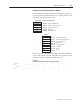
example of completed configuration,
3–4
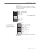
module ID code, 3–3
output image channel command, 3–6
SLC I/O image table, 3–4
C
contents of manual, P–2
D
datalinks, 4–2
definitions, P–3
DIP switch
configuration, 2–4
location, 2–1
E
enhanced mode
channel command output image, 4–9
configuring, 4–3
datalinks, 4–2
description of, 4–1
examples, 4–16– 4–25
G files, 4–10
M files, 4–11
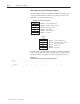
module ID code, 4–4
status field definitions, 4–8
error codes, B–29
G
G files
configuring, 4–10, A–9
description of, 4–10, A–8
editing file data, A–10
L
LED states, 5–1
M
M files
addressing, A–2
restrictions on, A–3
capturing data, A–8
configuring, A–1
description of, 4–11
M0 file image, 4–12
M0 files, explained, A–1
M0 message field, 4–14
M1 file image, 4–13
M1 files, explained, A–1
minimizing scan time, A–7
monitoring bit addresses, A–3
transferring data, A–4
access time, A–5
messaging, 4–3
available SCANport messages, B–4
error codes, B–29
example SLC program, B–4
message and reply structures, B–1
Read Enum String for Value in
Parameter, B–18
Read Full Parameter, B–11–B–15
scaling formulas, B–13
Read Number of Parameters, B–7
Read Parameter Link from Parameter
Number, B–27
Read Parameter Name Text, B–9
Read Parameter Value, B–8
Read Product Number, B–19
Read Product Series Number, B–21
Read Product Software Version, B–22
Read Product Text, B–20
Restore Parameter Values from
Non–volatile Storage, B–16
Save Parameter Values to Non–volatile
Storage, B–17
Scattered Read, B–23–B–25
Scattered Write, B–25–B–27
Set Default Parameter Values,
B–15–B–17
Write Parameter Link from Parameter
Number, B–28
Write Value to Parameter, B–10
module ID code
for basic mode, 3–3
for enhanced mode, 4–4
Index