
User Manual

3–6 Using Basic Mode
Publication 1203–5.9 –– October 1996
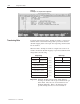
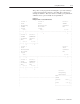
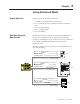
Channel Command Output Image Definitions
The Output Image Channel Command bits are defined as follows:
Not Used Not Used
Not Used
Channel 2 Command
Bit
15 14 13 12 11 10 9 8 76543210
DE
2
DE
1
DE
3
Word 0
Word 1
Channel 1 Command
Channel 3 Command
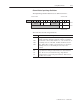
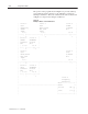
These bits have the following definitions:
DE1
DE2
DE3
SCANport Channel 1, 2, or 3 Data Enable bit. While low (0),
the channel will not transfer I/O data between the module and
the connected SCANport device. When high (1), the channel
becomes active to the SCANport device and transfers the
appropriate I/O data. When reset to low (0), the channel
disconnects from the SCANport device. This usually causes
the connected SCANport device to fault.
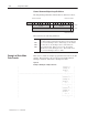
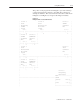
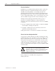
This section contains an example program that uses basic mode data
transfer. The following portion of the program enables all three
SCANport channels on the SLC to SCANport module.
Figure 3.6
Example of Enabling the SCANport Channels
| Channel 1 |
| SCANport |
| Enable |
| O:1.0 |
|––––––––––––––––––––––––––––––––––––––––––––––––––––––( )––––––|
| | 0 | |
| |Channel 2 | |
| |SCANport | |
| |Enable | |
| | O:1.0 | |
| +–––( )––––| |
| | 8 | |
| |Channel 3 | |
| |SCANport | |
| |Enable | |
| | O:1.1 | |
| +–––( )––––+ |
| 0 |
Example of Basic Mode
Data Transfer