
User Manual

3–5Using Basic Mode
Publication 1203–5.9 –– October 1996
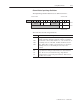
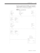
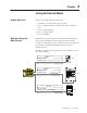
Channel Status Input Image Definitions
The Input Image Channel Status bits are defined as follows:
Not Used Not Used
Not Used
Channel 2 Status
Bit
15 14 13 12 11 10 9 8 765432 1 0
V2 ID2 V1 ID1
V3 ID3
Word 0
Word 1
Channel 1 Status
Channel 3 Status
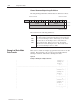
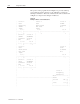
These bits have the following definitions:
This: Represents:
ID1
ID2
ID3
SCANport Channel 1, 2, or 3 Connected Adapter Port ID
Number. This three bit field contains the adapter port number
read from the connector that channel 1, 2, or 3 is connected to on
the SCANport device. ID1, ID2, and ID3 should be between 1
and 7. If ID1, ID 2, or ID3 is 7, the channel is not connected to
a SCANport device, or the SCANport device may not be
powered.
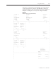
V1
V2
V3
SCANport Channel 1, 2, or 3 Valid Data bit. When high (1), the
Logic Status and Analog Feedback values are valid and can be
used. The V1, V2, and V3 bit will only go high after the
program sets the corresponding data enable bit. When low (0),
the values are not valid.