
User Manual

3–4 Using Basic Mode
Publication 1203–5.9 –– October 1996
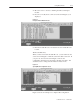
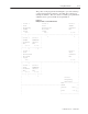
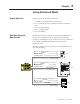
Figure 3.5
An Example of a Completed I/O Configuration
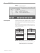
To transfer data using the SLC to SCANport module, you need to be
familiar with how the SLC I/O image table represents the internal
data I/O mapping and how the input and output image channel status
bits are defined.
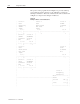
When the SLC to SCANport module is configured as a basic mode
module, the internal data I/O mapping is represented within the SLC
image table as the following:
Channel 2 Cmd Channel 1 Cmd
Reserved Channel 3 Cmd
Logic Command Channel 1
Analog Reference Channel 1
Logic Command Channel 2
Analog Reference Channel 2
Logic Command Channel 3
Analog Reference Channel 3
Channel 2 Stat Channel 1 Stat
Not Used Channel 3 Stat
Logic Status Channel 1
Analog Feedback Channel 1
Logic Status Channel 2
Analog Feedback Channel 2
Logic Status Channel 3
Analog Feedback Channel 3
Output Image Input Image
Word 0
Word 3
Word 1
Word 4
Word 2
Word 5
Word 6
Word 7
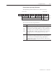
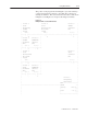
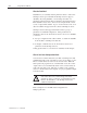
Important: Different SCANport devices may define different
meanings for the bits in the Logic Command and Logic
Status fields. They may also use the Reference and
Feedback differently. Refer to the manual for the
specific SCANport device for more information.
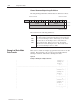
Transferring Data