
User Manual

Chapter
3
Publication 1203–5.9 –– October 1996
Using Basic Mode
Chapter 3 covers the following information:
• a description of what basic mode provides
• how to configure the SLC to SCANport module for basic mode
• how to transfer data
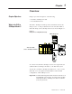
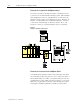
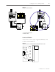
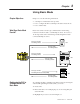
Basic mode sends a 16–bit logic command and a 16–bit analog
reference from the module to each SCANport device. It receives a
16–bit logic status and a 16–bit analog feedback signal from each
connected SCANport device.
INPUT OUTPUT SCANport
Channel 1
Channel 2
Channel 3
CHANNEL 1
CHANNEL 2
CHANNEL 3
SLC 5/01 CPU
PC RUN
CPU Fault
FORCED I/O
BATTERY LOW
POWER
08
19
210
311
715
614
513
412
08
19
210
311
715
614
513
412
16-bit logic command
16-bit analog reference
16-bit logic status
16-bit analog feedback
16-bit logic command
16-bit analog reference (not used by SMC)
16-bit logic status
16-bit analog feedback
16-bit logic command
16-bit analog reference
16-bit logic status
16-bit analog feedback
1305
1336
SMC
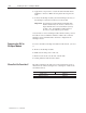
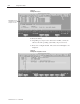
To configure the SLC to SCANport module for basic mode using the
Advanced Programming Software (APS), you need to:
1. Create a file.
2. Enter a file name. For example purposes, we are using SM1_AP
as the file name.
3. Highlight the processor as shown in Figure 3.1.
Chapter Objectives
What Does Basic Mode
Provide?
Configuring the SLC to
SCANport Module for
Basic Mode