
User Manual

2–5Installing the SLC to SCANport Module
Publication 1203–5.9 –– October 1996
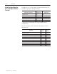
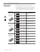
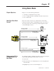
Set this DIP switch: To:To these settings:
Switches 7 and 8
12345678
O
P
E
N
O
–
12345678
SW7 SW8
Open Open
(Off) (Off)
Reserved
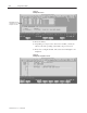
If you select a state other than Fault, the channel enable bits located
in the first two words of output data will retain their last state values.
This ensures that the enabled SCANport connections remain active
for those states. The I/O data transferred to the SCANport device
will change as configured by the DIP switch.
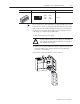
2. Turn off the chassis power supply.
!
ATTENTION: Do not install the SLC to SCANport
module with the chassis power supply on. Inserting or
removing the module with the chassis power supply on
may damage the module.
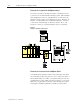
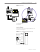
3. Select a slot for the module in the chassis. You may use any slot
except the leftmost slot, which is reserved for the SLC 5/xx
processor or rack adapter.
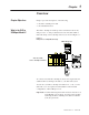
4. Insert the module into the slot you have selected.
CHANNEL 1
CHANNEL 2
CHANNEL 3
Channel 1
Channel 2
Channel 3
"