
User Manual
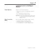

2–4 Installing the SLC to SCANport Module
Publication 1203–5.9 –– October 1996
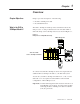
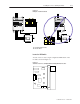
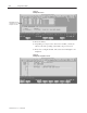
To install the SLC to SCANport module into the chassis:
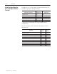
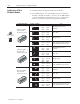
1. Set the DIP switches. For each SCANport device connected to
the SLC to SCANport module, you need to set two DIP switches
to select what happens when the SLC processor or rack adapter
faults or is placed in program for the appropriate channel.
Set this DIP switch: To these settings: To:
Channel 1 Fault/
O
–
12345678
SW1 SW2
Open Open
(Off) (Off)
Fault SCANport device
(default)
Program State
(Switches 1 and 2)
O
–
12345678
SW1 SW2
Closed Open
(On) (Off)
Zero data
2
345678
OPEN
O
–
12345678
SW1 SW2
Open Closed
(Off) (On)
Hold last state
12
3
O
–
12345678
SW1 SW2
Closed Closed
(On) (On)
Safe state data (enhanced mode
only), Fault (basic mode only)
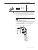
Channel 2 Fault/
O
–
12345678
SW3 SW4
Open Open
(Off) (Off)
Fault SCANport device
(default)
Program State
(Switches 3 and 4)
O
–
12345678
SW3 SW4
Closed Open
(On) (Off)
Zero data
2
345678
OPEN
O
–
12345678
SW3 SW4
Open Closed
(Off) (On)
Hold last state
12
3
O
–
12345678
SW3 SW4
Closed Closed
(On) (On)
Safe state data (enhanced mode
only), Fault (basic mode only)
Channel 3 Fault/
O
–
12345678
SW5 SW6
Open Open
(Off) (Off)
Fault SCANport device
(default)
Program State
(Switches 5 and 6)
O
–
12345678
SW5 SW6
Closed Open
(On) (Off)
Zero data
2
345678
OPEN
O
–
12345678
SW5 SW6
Open Closed
(Off) (On)
Hold last state
12
3
O
–
12345678
SW5 SW6
Closed Closed
(On) (On)
Safe state data (enhanced mode
only), Fault (basic mode only)
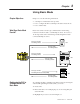
Installing the SLC to
SCANport Module
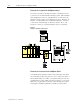
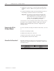
12
Switch 1 = Open (Off)
Switch 2 = Closed (On)
O
N
O
F
F