
User Manual

2–3Installing the SLC to SCANport Module
Publication 1203–5.9 –– October 1996
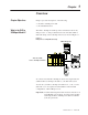
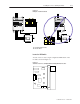
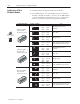
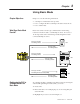
Figure 2.2
Examples of Cable Placements
SCANport
Channel 1
Channel 2
Channel 3
CHANNEL 1
CHANNEL 2
CHANNEL 3
SLC 5/01 CPU
PC RUN
CPU Fault
FORCED I/O
BATTERY LOW
POWER
A
B
A = Communications wire
B = Power wires
SCANport
Channel 1
Channel 2
Channel 3
CHANNEL 1
CHANNEL 2
CHANNEL 3
SLC 5/01 CPU
PC RUN
CPU Fault
FORCED I/O
BATTERY LOW
POWER
A
B
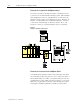
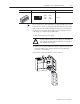
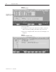
Locate the DIP Switch
You also need to locate a single configuration DIP switch on the
module as shown in Figure 2.3.
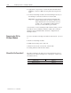
Figure 2.3
Side View of the SLC to SCANport Module Showing DIP Switch Location
1 7 865432
OPEN