
User Manual

Chapter
1
Publication 1203–5.9 –– October 1996
Overview
Chapter 1 provides descriptions of the following:
• the SLC to SCANport module
• the available functions
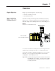
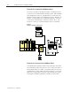
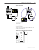
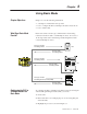
The SLC to SCANport module provides an interface between any
SLC processor or other product that can control modules within a
SLC rack and up to three SCANport devices as shown in Figure 1.1.
Figure 1.1
Example SLC to SCANport Module Set Up
INPUT OUTPUT SCANport
Channel 1
Channel 2
Channel 3
CHANNEL 1
CHANNEL 2
CHANNEL 3
SLC 5/01 CPU
PC RUN
CPU Fault
FORCED I/O
BATTERY LOW
POWER
08
19
210
311
715
614
513
412
08
19
210
311
715
614
513
412
SLC Rack with
SLC to SCANport Module
SMC Dialog Plus
1305
1336 PLUS
To connect more than three SCANport devices in a single rack, add
additional SLC to SCANport modules to your SLC rack system.
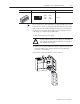
You can use your SLC to SCANport module in a 4, 7, 10, or 13 slot
SLC rack or a 2–slot expansion rack available for the fixed I/O
configurations of SLC–500 processors.
Important: An SLC rack using this module needs an enclosure of at
least 200 mm (8 in) in depth. You cannot place an SLC
rack using the SLC to SCANport module in a 150 mm
(6 in) deep enclosure.
Chapter Objectives
What is the SLC to
SCANport Module?