
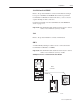
User guide


4–4 Configuring and Interfacing
1203–5.5 September 1995
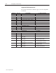
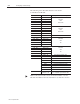
Important: The following two tables list the typical control and
status structure. You should refer to your drive manual
for the actual control and status structures for your
device.
The following are the bit definitions for B3:0 or writes to N41:0:
Bit Description Bit Description
00 Stop 10 Acceleration time
01 Start 11 Acceleration time
02 Jog 12 Deceleration time
03 Clear faults 13 Deceleration time
04 Direction 14 Reference select
05 Direction 15 Reference select
06 Local 16 Reference select
07 MOP increment 17 MOP decrement
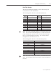
The following are the bit definitions for B3:10 or reads from N41:0:
Bit Description Bit Description
00 Enabled 10 At speed
01 Running 11 Local
02 Command direction 12 Local
03 Actual direction 13 Local
04 Accelerating 14 Reference select
05 Decelerating 15 Reference select
06 Alarm 16 Reference select
07 Faulted 17 Reference select