Allen-Bradley Bulletin 1203 Serial Communications Module (Series B) RS232/422/483 (Using DF1 Protocol) DH485 (Cat. No.
Important User Information Solid state equipment has operational characteristics differing from those of electromechanical equipment. “Safety Guidelines for the Application, Installation and Maintenance of Solid State Controls” (Publication SGI-1.1) describes some important differences between solid state equipment and hard–wired electromechanical devices.
Table of Contents Preface Who Should Use this Manual . . . . . . . . . . . . . . . . . . . . . . . . . . . . Purpose of this Manual . . . . . . . . . . . . . . . . . . . . . . . . . . . . . . . . . Contents of this Manual . . . . . . . . . . . . . . . . . . . . . . . . . . . . Related Documentation . . . . . . . . . . . . . . . . . . . . . . . . . . . . Terms and Abbreviations . . . . . . . . . . . . . . . . . . . . . . . . . . . . . . . Conventions . . . . . . . . . . . . . . . . . . . . . . . . . . . . .
ii Table of Contents SCANport Datalink Operation Chapter 3 Configuring and Interfacing Chapter 4 Chapter Objectives . . . . . . . . . . . . . . . . . . . . . . . . . . . . . . . . . . . SCANport Datalinks . . . . . . . . . . . . . . . . . . . . . . . . . . . . . . . . . . . Chapter Objectives . . . . . . . . . . . . . . . . . . . . . . . . . . . . . . . . . . . Serial Communications Module Data Table Structure . . . . . . . . . . . Supported PCCC Command List . . . . . . . . . . . . . . . . . . . . .
Preface Preface Read this preface to familiarize yourself with the rest of the manual. This preface covers the following topics: • who should use this manual • the purpose of this manual • terms and abbreviations • conventions used in this manual • safety precautions • Allen–Bradley support Who Should Use this Manual Use this manual if you are responsible for setting up and servicing the Serial Communications Module.
P–2 Contents of this Manual Chapter Title Contents Preface Describes the purpose, background, and scope of this manual. Also specifies the audience for whom this manual is intended. 1 Product Description Explains the Serial Communications Module’s features, configuration, and diagnostics. 2 Installation Provides procedures for mounting, connecting power, configuring switches, cabling, and connecting hardware.
Preface Terms and Abbreviations P–3 The following terms and abbreviations are specific to this product. For a complete listing of Allen–Bradley terminology, refer to the Allen–Bradley Industrial Automation Glossary, Publication Number ICCG–7.1. In this manual, we refer to the: • Variable Frequency AC Drive (Bulletin 1305, 1336 FORCE, 1336 PLUS, 1395, 1557, SMC, SMC Plus, or SMC dialog) as the drive or SCANport device. • Programmable Logic Controller as the Programmable Controller or PLC.
P–4 Serial Device Compatibility Allen–Bradley Support This Serial Communications Module is intended for use with devices that communicate via the following protocols: Hardware Standard Communications Protocol RS–232 DF1 RS–422 DF1 RS–485 DF1 DH–485 DH–485 Allen–Bradley offers support services worldwide, with over 75 Sales/Support Offices, 512 authorized Distributors, and 260 authorized Systems Integrators located throughout the United States alone, plus Allen–Bradley representatives in every ma
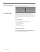
Chapter 1 Product Description Chapter Objectives In this chapter, you will read about: • Serial Communications Module features • the location of configuration switches Module Description The Serial Communications Module is an optional interface device designed to provide a direct digital link between serial communications devices and any device that uses SCANport.
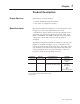
1–2 Product Description SCANport Device Compatibility The SCANport Serial Communications Module is compatible with the following Allen–Bradley devices: Device Firmware Revision 1336 PLUS All 1336 FORCE All 1305 Micro Drive 2.0 or newer SMC SMP 1394 1557 1203–5.
Product Description 1–3 Figure 1.1 Open Style Communications Module J4 SW1.1 – SW1.2 = Protocol select SW1.3 – SW1.8 = Adapter address 1 2 3 4 5 6 7 8 SW2.1 – SW2.3 = Baud rate selection SW2.4 = Parity enable SW2.5 = Parity sense (even/odd) SW2.6 = Stop bits SW2.7 = Point-to-point/multi-drop SW2.8 = CRC/BCC check 1 2 3 4 5 6 7 8 SW2 1 2 3 4 5 6 7 8 SW3 SW3.1 = Logic command/status and reference/feedback SW3.2 = Datalink A settings SW3.3 = Datalink B settings SW3.4 = Datalink C settings SW3.
1–4 Product Description Figure 1.2 Enclosed Style Serial-to-SCANport Communications Module SCANport connector Serial channel D-shell connector Power connection Diagnostic LEDs RX SCANport Status 1. LED off: adapter power removed 2. LED flashing green: link OK, not connected 3. LED solid green: link OK, connected 4. LED flashing red: was connected, now not connected 5. LED solid red: fault TX Serial Status 1. LED off: adapter power removed 2. LED flashing green: link OK, off–line 3.
Product Description 1–5 Figure 1.3 Typical Serial Communications/SCANport Device Interconnect PLC Open Style Comm Module .. . 1336 PLUS Serial port 1305 Micro Drive PC SCANport Serial communications link Serial Communications Module SLC 5/03 SLC 5/03 CPU SMP 3 SCANport Serial Communications Module Other serial devices AB0396C 1203–5.
1–6 Product Description Configuration Switches The Serial Communications Module contains three DIP Switches: SW1, SW2, and SW3 (Figure 1.1 and Figure 1.2). Switches are set ON or OFF as shown in Figure 1.4. For a detailed explanation of switch configuration, refer to Chapter 2. Figure 1.4 Configuration Switches Rocker switch Side view of typical switches Open Side switch Open Open (Off) Open Switch designation as shown in this manual Close (On) Off Open On AB0397A 1203–5.
Chapter 2 Installation Chapter Objectives In this chapter, you will learn how to: • • • • • set the module configuration switches mount the Serial Communications Module connect the cables connect the SCANport link connect the power supply Read this chapter completely before you attempt to install or configure your Serial Communications Module. Double check all connections and option selections before you apply power. Important: Switch selections take effect only on power–up.
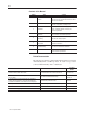
2–2 Installation Factory Switch Settings The following table shows the switch settings that are set at the factory: Switch Setting Communication Mode SW3–8 SW3–7 Off Off Default application timeout disabled SW3–6 Off Duplicate message detection disabled SW3–5 Off Datalink D disabled SW3–4 Off Datalink C disabled SW3–3 Off Datalink B disabled SW3–2 Off Datalink A disabled SW3–1 Off Logic command/status and reference/feedback disabled SW2–8 Off BCC checksum SW2–7 Off Point–to–po
Installation 2–3 Switch SW1 Switch SW1 is used to select: • serial communications mode (RS–232/RS–422/RS–485/DH–485) • Serial Communications Module address SW1 O F F O N 8 7 6 5 4 3 Communications Module Address 2 1 Protocol Selection AB0398B Use SW1–1 and SW1–2 to select the communications protocol you are using: Switch Value (Decimal) 0 SW1 O – Protocol RS–232 (DF1 protocol) 8 7 6 5 4 3 2 1 1 O – RS–422 (DF1 protocol) 8 7 6 5 4 3 2 1 2 O – RS–485 (DF1 protocol) 8 7 6 5 4 3 2 1 3
2–4 Installation Use SW1–3, SW1–4, SW1–5, SW1–6, SW1–7, and SW1–8 to set your address for the Serial Communications Module. The following table provides the switch settings for selecting the serial device addressing. " Note: If you are using the DH–485 communications mode, the highest serial device address you can select is 31 (decimal).
Installation 2–5 ÁÁÁÁ ÁÁÁÁÁ ÁÁÁÁÁ ÁÁÁ ÁÁÁÁ ÁÁÁÁÁ ÁÁÁÁÁ ÁÁÁÁ ÁÁÁÁÁ ÁÁÁÁÁ ÁÁÁ ÁÁÁÁ ÁÁÁÁÁ ÁÁÁÁÁ ÁÁÁÁ ÁÁÁÁÁ ÁÁÁÁÁ ÁÁÁ ÁÁÁÁ ÁÁÁÁÁ ÁÁÁÁÁ ÁÁÁÁ ÁÁÁÁÁ ÁÁÁÁÁ ÁÁÁ ÁÁÁÁ ÁÁÁÁÁ ÁÁÁÁÁ ÁÁÁÁ ÁÁÁÁÁ ÁÁÁÁÁ ÁÁÁ ÁÁÁÁ ÁÁÁÁÁ ÁÁÁÁÁ ÁÁÁÁ ÁÁÁÁÁ ÁÁÁÁÁ ÁÁÁ ÁÁÁÁ ÁÁÁÁÁ ÁÁÁÁÁ ÁÁÁÁ ÁÁÁÁÁ ÁÁÁÁÁ ÁÁÁ ÁÁÁÁ ÁÁÁÁÁ ÁÁÁÁÁ ÁÁÁÁ ÁÁÁÁÁ ÁÁÁÁÁ ÁÁÁ ÁÁÁÁ ÁÁÁÁÁ ÁÁÁÁÁ ÁÁÁÁ ÁÁÁÁÁ ÁÁÁÁÁ ÁÁÁ ÁÁÁÁ ÁÁÁÁÁ ÁÁÁÁÁ ÁÁÁÁ ÁÁÁÁÁ ÁÁÁÁÁ ÁÁÁ ÁÁÁÁ ÁÁÁÁÁ ÁÁÁÁÁ ÁÁÁÁ ÁÁÁÁÁ ÁÁÁÁÁ ÁÁÁ ÁÁÁÁ ÁÁÁÁÁ ÁÁÁÁÁ ÁÁÁÁ ÁÁÁÁÁ ÁÁÁÁÁ ÁÁÁ ÁÁÁÁ ÁÁÁÁÁ ÁÁÁÁÁ ÁÁÁÁ ÁÁÁÁÁ ÁÁÁÁÁ ÁÁÁ ÁÁÁÁ ÁÁÁÁÁ ÁÁÁÁÁ
2–6 Installation Switch SW2 Switch SW2 is used to select: • • • • • baud rate parity number of stop bits point–to–point or multi–drop checksum mode (CRC or BCC) SW2 O F F O N 8 7 6 5 4 Parity setting 3 2 1 Baud rate selection Stop bits Point-to-point/multi-drop Checksum mode AB0399A Use SW2–3, SW2–2, and SW2–1 to select the baud rate: ÁÁÁÁÁ ÁÁÁÁÁ ÁÁÁÁÁÁ ÁÁÁÁÁ ÁÁÁÁÁ ÁÁÁÁÁÁ ÁÁÁÁÁ ÁÁÁÁÁ ÁÁÁÁÁÁ ÁÁÁÁÁ ÁÁÁÁÁ ÁÁÁÁÁÁ ÁÁÁÁÁ ÁÁÁÁÁ ÁÁÁÁÁÁ ÁÁÁÁÁ ÁÁÁÁÁ ÁÁÁÁÁÁ ÁÁÁÁÁ ÁÁÁÁÁ ÁÁÁÁÁÁ ÁÁÁÁÁ ÁÁÁÁÁ ÁÁÁÁÁÁ ÁÁÁÁÁ
Installation " 2–7 Note: If you are using the DH–485 communications mode, setting switches SW2–4, SW2–5, SW2–6. SW2–7, and SW2–8 have no effect because this information is selected within the software.
2–8 Installation Switch SW3 Switch SW3 is used to select: • • • • logic command/status and reference/feedback datalinks (up to four datalinks) duplicate message detection application timeout default value SW3 O F F O N 8 7 6 5 4 3 2 1 Datalink message Application timeout enables default values Logic command/ Duplicate message status and reference/ detection feedback AB0400B Use SW3–1 to enable and disable the logic command/status and reference/feedback messaging: SW3 O – Function Disable log
Installation 2–9 Use SW3–4 to enable and disable Datalink C messaging: SW3 O – Function Disable Datalink C messaging. 8 7 6 5 4 3 2 1 O – Enable Datalink C messaging. 8 7 6 5 4 3 2 1 Use SW3–5 to enable and disable Datalink D messaging: SW3 O – Function Disable Datalink D messaging. 8 7 6 5 4 3 2 1 O – Enable Datalink D messaging. 8 7 6 5 4 3 2 1 Use SW3–6 to enable and disable duplicate message detection: SW3 O – Duplicate Message Detection Disable duplicate message detection.
2–10 Installation Mounting the Serial Communications Module The Serial Communications Module can be provided in three mounting configurations: • Open style board, factory installed in a drive (not available for all drives) • Open style board as a separate kit • Enclosed style for panel mount or DIN rail mount This section provides mounting information for the Open style kit and the Enclosed style. Open Style Communications Module Mounting Location (1336 PLUS 7.
Installation 2–11 Enclosed Style Communications Module Mounting Location (1336 FORCE and 1336 PLUS Drives) 1336 FORCE ESC SEL JOG Port Expander SCANport 2 2 4 3 5 Optional Male–Male Cable Communications Module Communications Module 1203–5.
2–12 Installation Enclosed Style Serial Communications Module Dimensions 44mm (1.75) Enclosed Style Serial Communications Module Dimensions DIN DINRail Rail Notes: – The enclosure requires clearance at the top and bottom for proper cooling. Additional space is required if you want to access the DIP switches without removing the device. – All dimensions are given in millimeters and (inches). 70mm (2.7) DIN Rail 45mm (1.8) DIN Rail Mounting Clip Top View Back View 45mm (1.8) 25mm (1) 76mm (3.
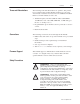
Installation Connecting Cables 2–13 This section provides information that you need to connect the cables to your Serial Communications Module. Important: When connecting your cables, you should make sure that the network is properly terminated. You should also ground the shield at the end furthest from the Serial Communications Module.
2–14 Installation IBM PC Compatible Serial Connections RS–485/RS–422/RS–232 Communications Adapter to IBM AT Compatible Computer RS–232 Serial Port Connection Diagram IBM AT Compatible Personal Computer Computer Internal RS232 Serial Port Jumper Connectors Communications Module 9-Pin D-Shell 1 COM N.C. TX N.C. RX N.C. N.C. N.C.
Installation 2–15 PLC5 Channel 0 Serial Connections Serial Communications Module to PLC5 RS–232 Serial Port Connection Diagram PLC5/20, 5/40, 5/60, 5/80 Channel 0 Communications Module 9-Pin D-Shell 1 2 1 COM N.C. TX N.C. RX N.C. N.C. N.C. COM 2 3 4 5 3 6 4 7 5 8 6 9 7 8 C.GND N.C. 14 TXD 15 RES RXD 16 N.C. RTS 17 RES CTS 18 RES DER 19 N.C. SG.GND DTR DCD RES RES N.C. N.C. N.C. RES RES RES RES N.C.
2–16 Installation SCANport Link Connection Cable Requirements SCANport cables are available in either male–to–male or male–to– female configuration. You can connect cables of up to 10 meters (33 feet) from the master to the SCANport device (A in the figure below). If you use a Port Expander (as shown in the figure below), you need to subtract the cable length from the master to the Port Expander from the cable length used to connect the device to the expander (B1 + C = a maximum of ten meters).
Installation 2–17 1336 PLUS and 1336 FORCE Refer to the product manual for connection information. On larger horsepower 1336 PLUS and FORCE drives with an open Serial Communications Module mounted in the drive, you do not need a separate SCANport cable connection. Connection information for the 1336 PLUS and 1336 FORCE is shown on page 2–11. Important: The maximum cable distance between any two devices cannot exceed 10 meters (33 feet) of cable.
2–18 Installation Power Supply Connections The Enclosed Communications Module is powered from a separate 24V DC or 115/230V AC power supply (as shown below). With the Open Style Communications Module board mounted in the drive, no separate power supply connections are required.
Chapter 3 SCANport Datalink Operation Chapter Objectives In this chapter, you will read about SCANport Datalinks. SCANport Datalinks A Datalink is a type of pointer function used by some SCANport devices to transfer parameter values to and from the SCANport device. The Datalink function transfers parameters on a regular schedule.
3–2 SCANport Data Link Operation 1203–5.
Chapter 4 Configuring and Interfacing Chapter Objectives This chapter provides you with information on how the Serial Communications Module communicates with a serial device. The following topics are explained: • Serial Communications Module data table structure • configuration examples ! Serial Communications Module Data Table Structure ATTENTION: When you configure a system for the first time, you should disconnect the motor from the machine or the process during the initial testing.
4–2 Configuring and Interfacing Supported PCCC Command List The Serial Communications Module supports the following PCCC Commands: CMD Code FNC Code 01h n/a Unprotected read PLC–2 address 06h 00h Echo n/a 01h Read diagnostic counters Variable (modified PLC–2 addresses) 02h Set variables (#ENQs, #NAKs, TIMEOUT) n/a 03h Identify host and some status n/a 04h Set timeout n/a 05h Set #NAKs n/a 06h Set #ENQs n/a 07h Reset diagnostic counters n/a 09h Read link parameters Logical
Configuring and Interfacing 4–3 Data Table Structure The Serial Communications Module provides the following data table structures for DF1 and DH–485. The following table is the drive control table (binary file).
4–4 Configuring and Interfacing Important: The following two tables list the typical control and status structure. You should refer to your drive manual for the actual control and status structures for your device.
Configuring and Interfacing 4–5 The following is the data table structure for PLC–2 style addressing: Parameter Number 1 – 7039 1 – 7039 " PLC–2 Style Address Decimal (Octal) 512 + Parm # (1000 to 16577) (16600 to 167770 Description of Location’s Purpose Parameter value read Status of last parameter write 7680 + Parm # (17000 to 34577) (34600 to 34677) Block transfer emulation area (34700) Logic command/status (34701) Reference/feedback (34702) Datalink A1 (34703) Datalink A2 (34704) Datal
4–6 Configuring and Interfacing The following is the data table structure for the Serial Communications Module: Parameter Number File Addresses Description of Location’s Purpose 1 – 999 1000 – 1999 N10:1 – 999 N11:0 – 999 Parameter – – value 8000 – 8999 N18:0 – 999 read or write 9000 – 9999 N19:0 – 999 1 – 249 N50:1 – 249 250 – 499 N51:0 – 249 – – value 9500 – 9749 N88:0 – 249 read or write 9750 – 9999 N89:0 – 249 N20:0 – 127 " 1203–5.
Configuring and Interfacing 4–7 The data tables have up to eight areas, each having a different purpose. 1. Parameter Value Read or Write (N10 – N19, N50 – N89). Reading data from files in this area will cause the Serial Communications Module to read parameter values from the SCANport device and send those values as the response to the read message. Writing data to files in this area will cause the Serial Communications Module to write that data into SCANport device parameters. 2.
4–8 Configuring and Interfacing – Datalink A1. Writing to Datalink A1 sends a value to the parameter pointed to by the DataIn A1 parameter of the SCANport device. Reading from Datalink A1 reads the value of the parameter pointed to by the DataOut A1 parameter of the SCANport device. – Datalink A2 through Datalink D2 function the same as Datalink A1. 6. Serial Communications Module Parameters (N42).
Configuring and Interfacing 4–9 Configuration Examples DF1 Messaging with a PLC–5/80 Example This example reads parameters 1 through 50.
4–10 Configuring and Interfacing Notes: • I:000/00 is any application–related conditioning logic. • MG20:0.EN is the enabled status bit from the message block. • B3/2 is a one-shot that causes the message to be resent each time • • • • • 1203–5.5 September 1995 the message block completes or errors (as long as I:000/00 is true). The DF1 address of the PLC-5 is the same as its DH+ address (set by DIP switch SW1 on the PLC-5). Refer to Publication 6200–6.4.
Configuring and Interfacing 4–11 DF1 Messaging with a 1746–BAS Module Example This example accepts a parameter number and a value from a user terminal and writes the data out to a SCANport–compatible device.
4–12 Configuring and Interfacing 550 560 561 562 563 565 570 580 600 610 620 630 640 650 660 670 680 690 700 710 720 730 750 760 REM **************************************************************** REM ********* PLC TYPED READ Subroutine ***** REM ********* inputs Parameter number in var PAR_NUM ***** REM ********* ASC coded hex string of value in $(1) ***** REM ********* outputs: failure message ***** REM **************************************************************** REM subroutine to do a typed write
Configuring and Interfacing 4–13 DH–485 Messaging with a SLC5/03 Interface The following example uses the DH–485 communications mode to send a message from an SLC5/03 to the Serial Communications Module. Rung 2:0 If this is the first scan or the error bit is true, the MSG instruction’s control byte is cleared and the done bit is set. This ensures that the program always starts correctly and recovers from a MSG error.
4–14 Configuring and Interfacing Rung 2:2 When the timer is done, the MSG instruction is enabled.
Chapter 5 Block Transfer Emulation Instructions Chapter Objectives This chapter contains the header and data configurations that you need to set up the data files for the block transfer emulation instructions. The header and data values depend on the operation you want to perform. Block Transfer Emulation Status Word When an operation is unsuccessful, header word 2 of the drive response contains a negative value (bit 15 = 1).
5–2 Scattered Parameter Value Read The Scattered Parameter Value Read function reads a scattered list of parameters. PLC Block Transfer Emulation Instruction Data PLC request instruction length: 5–63 words Drive response instruction length: 5–63 words Message Structure PLC Request Drive Response Message Length 5–63 Header Word 1 PLC Decimal Value 3 Header Word 2 Number of Parameter Values to Read Data Word 3 Parameter Number 1 Data Word 4 0 Data Word 5 Parameter Number 2 1203–5.
Block Transfer Emulation Instructions 5–3 Message Operation Scattered Parameter Value Read reads a pre–defined group of parameter values, in any order, from the device. You define the number of parameters to read in word 3 of the request. The parameters to be read and their order is defined starting with word 4. An unused word is left between each parameter request, so the drive can respond with the parameter value, as shown.
5–4 Scattered Parameter Value Write The Scattered Parameter Value Write function writes to a scattered list of parameters and returns the status of each parameter. If any of the states have errors, the parameter number is negative. PLC Block Transfer Emulation Instruction Data PLC request instruction length: 5–63 words Drive response instruction length: 5–63 words Message Structure PLC Request Drive Response 1203–5.
Block Transfer Emulation Instructions 5–5 Message Operation The Scattered Parameter Value Write function writes data values to a pre–defined group of device parameters in any order. You define the number of parameters to write in word 3. The parameters to be written to and their order is defined starting with word 4. If an error occurs while writing to any of the parameters: • Word 2 of the drive response returns a value of –32765. • Bit 15 of the drive response word for that parameter’s number is set.
5–6 Product ID Number Read The Product ID Number Read function returns the product ID of the device to which the Serial Communications Module is connected.
Block Transfer Emulation Instructions 5–7 Example In this example, the Product ID Number Read was requested. The drive response contained a value of 3 in word 4 of its message response, indicating a connection to a 1336 PLUS. Data File Format PLC request Drive response N10:0 N10:90 0 1 2 3 256 0 6 256 0 3 4 5 6 7 8 9 3* * Example only – These values vary depending on parameters and products. 1203–5.
5–8 Parameter Read Full The Parameter Read Full function provides all known attributes for the parameters requested. This information includes the parameter’s current value, descriptor, multiply and divide value, base value, offset value, text string, group element reference, minimum value, maximum value, default value, and unit text string.
Block Transfer Emulation Instructions 5–9 Message Structure (Continued) Drive Response File, Group, Element Data Word 15 Minimum Value Data Word 16 Maximum Value Data Word 17 Default Value Data Word 18 Unit Text Char 2 Char 1 Data Word 19 Unit Text Char 4 Char 3 Data Word 20 Message Operation Parameter Read Full retrieves the attributes of the specified parameter. The attributes for each parameter include the data, minimum and maximum values, and the parameter text.
5–10 This example shows the response message N10:90 through N10:112 in both binary and ASCII. Note the ASCII information beginning with N10:99. The parameter name characters return in reverse order for each word. N10:99 has the ASCII value of (aM). To read this, invert the word to read (Ma). The next word (ix), inverted gives you (xi). These words, along with the following two words, form the word Maximum. You can see the parameter name Maximum Voltage in word 7 through word 14 of the response message.
Block Transfer Emulation Instructions Parameter Value Read 5–11 The Parameter Value Read function reads the 16–bit parameter data value for the selected parameter number.
5–12 Parameter Value Write The Parameter Value Write message writes a 16–bit parameter data value to the selected parameter number.
Block Transfer Emulation Instructions EE Memory Functions 5–13 The EE Memory Functions message activates the specified EE functions.
5–14 Example This example requests that an EEPROM Save function be performed. Data File Format PLC request Drive response N10:10 N10:90 0 1 2 3 4 –31998 0* 1* 3 770 0* 4 * Example only – These values vary depending on parameters and products. 1203–5.
Block Transfer Emulation Instructions Fault Clear/Reset 5–15 The Fault Clear/Reset message activates the Clear Fault, Clear Fault Queue, and Drive Reset functions.
5–16 Fault Queue Entry Read Full This function reads the contents of the specified fault queue entry. A message is returned which includes the fault text and fault code associated with the specified fault queue entry. The 1336 FORCE also returns the time stamp associated with the fault.
Block Transfer Emulation Instructions 5–17 Message Operation Fault Queue Entry Read Full reads the contents of the fault queue specified in word 3 of the request. The response returns the fault text which can be ASCII text. The text will have every two characters in reverse order. In addition, the 1336 FORCE returns a time stamp, indicating the day and time the fault occurred. If an error has occurred, word 2 of the response returns a negative value.
5–18 Fault Queue Size The Fault Queue Size function gets the number of fault entries allowed in the fault queue.
Block Transfer Emulation Instructions Trip Fault Queue Number 5–19 The Trip Fault Queue Number provides the fault queue number of the fault that caused the device to trip.
5–20 1203–5.
Chapter 6 Troubleshooting Chapter Objectives Use this chapter to help you troubleshoot your Serial Communications Module system using the LED indicators on the front of the device (as shown below). The Serial Communications Module is a non-serviceable device that you should return to Allen-Bradley for replacement when a major fault exists that is attributable to the Serial Communications Module itself.
6–2 Troubleshooting ! ! ATTENTION: Servicing energized industrial control equipment can be hazardous. Electrical shock, burns, or unintentional actuation of controlled industrial equipment may cause death or serious injury. Follow the safety-related practices of NFPA 70E, Electrical Safety for Employee Workplaces, when working on or near energized equipment. Do not work alone on energized equipment. ATTENTION: Do not attempt to defeat or override fault circuits.
Chapter 7 Specifications Chapter Objectives This chapter provides you with background information and specifications that you may need to install or apply your Serial Communications Module.
7–2 Specifications 1203–5.
Allen-Bradley, a Rockwell Automation Business, has been helping its customers improve productivity and quality for more than 90 years. We design, manufacture and support a broad range of automation products worldwide. They include logic processors, power and motion control devices, operator interfaces, sensors and a variety of software. Rockwell is one of the worlds leading technology companies. Worldwide representation.