Bulletin 1203 Serial Communications Module PPG OPTOMUX Catalog Number 1203-GD9, –GK9 User Manual
Important User Information Because of the variety of uses for this equipment and because of the differences between this solid-state equipment and electromechanical equipment, the user of and those responsible for applying this equipment must satisfy themselves as to the acceptability of each application and use of the equipment. In no event will Allen-Bradley Company be responsible or liable for indirect or consequential damages resulting from the use or application of this equipment.
Summary of Changes Summary Information Information for the –GK9 module was added to this manual.
Summary of Changes This Page Intentionally Left Blank
Table of Contents Introduction Chapter 1 Manual Objectives . . . . . . . . . . . . . . . . . . . . . . . . . . . . . . . . . . . . . . . . Who Should Use This Manual . . . . . . . . . . . . . . . . . . . . . . . . . . . . . . . Vocabulary . . . . . . . . . . . . . . . . . . . . . . . . . . . . . . . . . . . . . . . . . . . . . . Firmware Support . . . . . . . . . . . . . . . . . . . . . . . . . . . . . . . . . . . . . . . . Manual Organization . . . . . . . . . . . . . . . . . . . . . . . . . . . . . . .
Table of Contents This Page Intentionally Left Blank.
Chapter 1 Introduction Manual Objectives The purpose of this manual is to provide you with the necessary information to apply the Serial Communications Module which is available for products that include the SCANportt communications port. Described in this manual are methods for installing, configuring, and troubleshooting the Serial Communications Module. For information on specific features of Allen-Bradley products mentioned herein, refer to the product user manual.
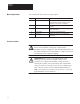
Chapter 1 Introduction Manual Organization This manual is divided into the following chapters.
Chapter 2 Product Description Chapter Objectives In this chapter, you will read about: Communications module features Location of configuration switches Module Description This module is designed to be used with the 1336-EN20. It is not compatible with any other SCANport devices.
Chapter 2 Product Description Figure 2.
Chapter 2 Product Description Configuration Switches The Serial Communications Module has three DIP Switches: SW1, SW2, and SW3 (Figure 2.1). Switches are set ON or OFF as shown in Figure 2.2. For a detailed explanation of switch configuration, refer to Chapter 3, Installation. Figure 2.
Chapter 2 Product Description This Page Intentionally Left Blank.
Chapter 3 Installation Chapter Objectives In this chapter you will learn how to: Mount the communications module Configure the communications module Connect power Connect SCANport and serial communications cables Read this chapter completely before you attempt to install or configure your communications module. Double check all connections and option selections before you apply power. Important: Switch selections take effect only on power-up.
Chapter 3 Installation Factory Switch Settings 3-2 Switch Setting Communication Mode SW1-8 Off SW1-7 Off SW1-6 Off SW1-5 Off SW1-4 Off SW1-3 Off SW1-2 Off SW1-1 On SW2-8 Off Speed Limit Check SW2-7 Off Not Used SW2-6 On Protocol Selection SW2-5 On Parity Enabled SW2-4 On Odd Parity (if enabled) SW2-3 On SW2-2 On SW2-1 On SW3-8 Off SW3-7 Off SW3-6 Off SW3-5 Off SW3-4 Off SW3-3 Off SW3-2 Off SW3-1 Off Drive Number = 1 RS RS422 19.
Chapter 3 Installation Switch SW1 Switch SW1 selects: Communications mode selection (RS232/RS422/RS485) Communications module address SW1 O F F O N 8 7 6 5 4 Communications Module Address 3 2 1 Communications Mode Selection AB0398B Table 3.
Chapter 3 Installation Table 3.
Chapter 3 Installation Switch SW2 Switch SW2 selects the baud rate, parity, and speed limit. SW2 O F F O N 8 7 6 5 4 Parity Setting 3 2 1 Baud Rate Selection Protocol Selection Not Used Speed Limit AB0492B Table 3.
Chapter 3 Installation Switch SW3 Switch SW3 selects Stop Bits. SW3 O F F O N 8 7 6 5 4 3 2 1 Set to Off Stop Bits AB0493A Table 3.G Switch SW3-1 – SW3-6 Settings ÁÁÁÁÁÁ ÁÁÁÁÁÁÁÁÁÁÁÁÁÁÁÁÁÁÁ ÁÁÁÁÁÁ ÁÁÁÁÁÁÁÁÁÁÁÁÁÁÁÁÁÁÁ ÁÁÁÁÁÁ ÁÁÁÁÁÁÁÁÁÁÁÁÁÁÁÁÁÁÁ ÁÁÁÁÁ ÁÁÁÁ ÁÁÁÁÁÁÁÁÁÁÁÁÁÁÁÁ ÁÁÁÁÁ ÁÁÁÁ ÁÁÁÁÁÁÁÁÁÁÁÁÁÁÁÁ ÁÁÁÁÁ ÁÁÁÁ ÁÁÁÁÁÁÁÁÁÁÁÁÁÁÁÁ ÁÁÁÁÁ ÁÁÁÁ ÁÁÁÁÁÁÁÁÁÁÁÁÁÁÁÁ ÁÁÁÁÁ ÁÁÁÁ ÁÁÁÁÁÁÁÁÁÁÁÁÁÁÁÁ ÁÁÁÁÁ ÁÁÁÁ ÁÁÁÁÁÁÁÁÁÁÁÁÁÁÁÁ SW3-1 – SW3-6 Function Off Must be set to Off position Table 3.
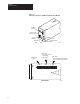
Chapter 3 Installation Enclosed Style Communications Module Dimensions Figure 3.1 Enclosed Style Communications Module Dimensions 44mm (1.75) DIN DINRAIL RAIL NOTES: 1. The enclosure requires clearance at the top and bottom for proper cooling. Additional space is required if access to DIP switches is desired without having to remove the device. 2. All dimensions in millimeters and (inches). 70mm (2.7) DIN RAIL 45mm (1.8) DIN Rail Mounting Clip TOP VIEW BACK VIEW 45mm (1.8) 25mm (1) 76mm (3.
Chapter 3 Installation Cable Connections RS485/RS422/RS232 Connection Examples Figure 3.2 RS232 Mode Port Connection Diagram Communications Module 9-Pin D-Shell 1 COM N.C. TX N.C. RX N.C. N.C. N.C. COM 2 3 4 5 6 7 8 9 AB0501A RS422 Mode Port Connection Diagram Communications Module 9-Pin D-Shell 1 COM RXD RXD N.C. SHIELD N.C. TXD TXD COM 2 3 4 5 6 7 8 9 AB0502A RS485 Mode Port Connection Diagram Communications Module 9-Pin D-Shell 1 COM N.C. N.C. N.C. SHIELD N.C.
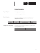
Chapter 3 Installation SCANport Link Connection Cable Requirements SCANport cables are available in either male–to–male or male–to–female configuration. Cables (C) of up to 10 meters (33 feet) can be connected from the master to the SCANport device. If a Port Expander (B1) is used, subtract the cable length from the master to the Port Expander from the cable length used to connect the device to the expander (B1 + C = maximum of 10 meters).
Chapter 3 Installation Power Supply Connections The enclosed communications module is powered from a separate 24V dc or 115/230V ac power supply (Figure 3.3). With the open-style communications module board mounted in the drive, no separate power supply connections are required. Figure 3.
Chapter Chapter 4 Troubleshooting Chapter Objectives Use this chapter to help troubleshoot your serial communications system using the LED indicators on the front of the device (Figure 4.1). The communications module is a non-serviceable device that should be returned to Allen-Bradley for replacement when a major fault exists that is attributable to the communications module itself. Figure 4.
Chapter 4 Troubleshooting Table 4.
Chapter 5 Specifications Chapter Objectives This chapter provides background information and specifications that you may need when installing or applying your communications module.
Chapter 5 Specifications This Page Intentionally Left Blank.
Index Index C Cable Connections, 3-8 Cable Requirements Cable length, 3-9 Port Expander, 3-9 SCANport, 3-9 M Manual Audience, 1-1 Objectives, 1-1 Organization, 1-2 Module Communication Compatibility, 5-1 Communications Module Compatibility, 5-1 Configuration Switches, 2-3 Device Compatibility, 2-1 Enclosed Style, 2-2 Enclosed Style Dimensions, 3-7 Product Description, 2-1 Product Specifications, 5-1 Setting Configuration Switches, 3-1 Module Configurations, Factory Switch Settings, 3-2 Connection Examp
Index This Page Intentionally Left Blank.
Notes N-1
Notes N-2
Notes N-3
Notes N-4
We Want Our Manuals to be the Best! You can help! Our manuals must meet the needs of you, the user. This is your opportunity to make sure they do just that. By filling out this form you can help us provide the most useful, thorough, and accurate manuals available. Please take a few minutes to tell us what you think. Then mail this form, FAX it, or send comments via E-Mail. FAX: to your local Allen-Bradley Sales Office or 414/242-8579 E-Mail: via Internet to “SEPATTER@ABPOST.remnet.ab.
FOLD HERE FOLD HERE NO POSTAGE NECESSARY IF MAILED IN THE UNITED STATES BUSINESS REPLY MAIL FIRST CLASS PERMIT NO. 413 MEQUON, WI POSTAGE WILL BE PAID BY ADDRESSEE ALLEN-BRADLEY Attn: Marketing Communications P.O.
SCANport is a trademark of Allen-Bradley Company, Inc.
Publication 1203-5.4 — April, 1996 Supersedes July, 1995 P/N 74002-125-01(B) Copyright 1994, Allen-Bradley Company, Inc.