
Owner's manual


2-2 Configuring the 1203-GK5 Module or 1336-GM5 Board
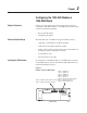
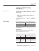
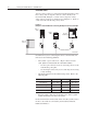
On the 1203-GM5 board, DIP switches are found in the following
location.
Figure 2.2
Switches on the 1336-GM5 Board
Configuring the 1203-GK5 Module
or 1336-GM5 Board
If you do not intend to use the factory-default settings, you must
configure the module using its DIP switches. Using the DIP switches,
you can configure the following features:
• DeviceNet network data rate.
• Node address for the adapter.
• Datalinks.
• Adapter reaction when the network fails.
• Adapter reaction when the controller is idle (e.g., scanner or
controller is in program mode).
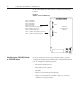
AB0938
SW1.1 = Datalink A
SW1.2 = Datalink B
SW1.3 = Datalink C
SW1.4 = Datalink D
SW1.5 = Not Used
SW1.6 = Zero Data / Hold Last State
SW1.7 = Fault on Comm Loss
SW1.8 = Fault On Pgm / Idle
SW2.1 – SW2.6 = Node Address Selection
SW2.7 – SW2.8 = Data Rate Selection
SW2
SW1
DeviceNet
Communications
Module
1
2
3
4
5
6
7
8
1
2
3
4
5
6
7
8